It’s not uncommon for production equipment operators to be concerned about lathe and spindle alignment. The tool moves in an axis that is no longer parallel with the centerline of the chuck that is holding the rotating workpiece. Operators suspect an alignment problem with a CNC turning center, lathe, or a spindle machine but they may continue along and just “hope for the best” since measuring the alignment error and correcting for it takes too long.
Lathe and spindle misalignments typically fall into two categories:
Offset or Centerline Misalignment
Offset or concentricity misalignments occur when the centerlines of the rotating spindle, chuck, tool holder or work piece holder are displaced from each other. Offset misalignments fall into 2 axes, typically referred to as X and Y or vertical and lateral across the Z axis of the machine bed. These centerline or offset errors tend to be constant and maintain a fixed error value as you travel further away from the chuck or tailstock.
Parallelism or Angular Misalignment
Parallelism misalignment occurs when the axis of the part rotation and the axis of tool movement are not parallel to each other. These errors can typically be quantified by an angular error value or a displacement error over a specific distance. The key attribute with angular errors is that they change with distance, so the further you move from the source (chuck or spindle), the greater the angular error becomes. Often, a machine tool will exhibit both of these misalignment errors requiring additional measuring and alignment procedures or machine tool compensation.
Relative to the machine bed and tool axis, the chuck or spindle is likely to have a little of each, both offset and angular misalignment. The position and orientation of the tailstock may also contribute to an offset as well as an angular error.
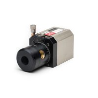
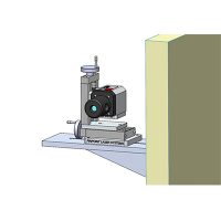
Ignoring a potential alignment issue and “hoping for the best” will almost always backfire. Parts will be cut to the wrong dimensions and may exhibit unwanted tapers and profiles when the machine is mis-aligned. Rotating machinery works best, runs more efficiently, and produces better quality parts when it is properly aligned. Machinery alignment doesn’t need to take too long or be too complex. Using the proper laser alignment equipment, alignment of spindle equipment is easy to perform and improves manufacturing efficiency and profits. By taking a number of measurements with the laser and receiver in various rotational positions you are able to measure the combined offset and angular errors described above. Then by moving the receiver to a new location and repeating the measurements we can determine the individual angular error. Simple processing functions can then calculate the offset errors and angular errors and provide guidance on how to correct the machine misalignments.