Straightness Data Routine
Data analysis and calculations for measuring straightness
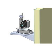
How to Measure Straightness With the Microgage

Step by Step Instructions
- Place receiver at Distance A, and record readings in table.
- Place receiver at Distance B, and record readings in table.
- The calculated rise over run is a factor that can now be applied to any measured distance.
- Record any further measurements in the table in increasing increments of distance, and the deviation from the calculated line will be reported.


Typical Linear Measurement Applications
- Measuring straightness of long machine beds
- Checking for runout on moving slides, tables and stages
- Measure bend and profiles in tracks and guide rails
- Shaft and drive alignment
- Positioning bearings and shaft supports over long runs
- Monitoring surface deflections and bending in long structures
- Aligning long rail and track sections
- Checking roll flatness and profiles
- Measuring deflections on rams, actuators, and extrusion presses
- Other measurement of linear deflections