ROI
App Chat
Free Report
Notes
Tips
FAQ
Videos
Items Needed
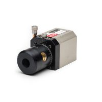
- Microgage 2D Alignment System
- 4 Axis Laser Mount
- Alignment Tripod
- Microgage Bore Mount
- Receiver Extension Cable
- Plastic Targets for Rough Alignment
- Tape Measure
- Notepad for results
Optional Items:
- Microgage 4D Receiver
- Laser Support Stand
[/row]Propeller Shaft Alignment – Forward Alignment Approach
This alignment technique uses a laser mounted in the region of the propeller and projects a laser reference beam forward. This laser reference beam passes through the strut tube or cutlass bearing, the stern tube, support bearings, if any, and to the engine or reduction gearbox.
When the laser beam is in place, centered, and aligned it can then be used for checking the placement and alignment of each part of the propulsion system.
Typically, the stern tube or perhaps the strut tube is fixed in place and the alignment of the propeller shaft is based on the orientation of one or both of these components. The angle of propeller shaft and its random orientation in space (depending on the location of the boat) means that the alignment of the laser beam will probably not be level to gravity or tied to convenient mechanical surfaces and features in the area. The objective for rough alignment is to get the laser beam as close to centerline and parallel with the shaft axis for either the strut tube or the stern tube.
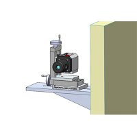
The Microgage Laser needs to be positioned at the aft end of the vessel and the laser beam directed along the center of the shaft run going forward. The laser transmitter is mounted onto the 4-Axis Mount and this assembly can in turn be mounted on the Alignment Tripod or on a solid mechanical stand. The angle of a propeller shaft can be anywhere from nearly parallel to as much as 40 degrees to the waterline of the vessel. The 4-Axis Mount provides very tight control of the laser transmitter in moving linearly up/down, as well as right/left and also allows for angular adjustment in these two axes as well. The angular range of motion is ~ + 4 degrees so the 4-Axis Mount will need to be pitched and secured in place for this alignment. Using the Alignment Tripod and adjusting the length of the extended legs can provide this desired angle of pitch. Placing a sand bag on the base of the tripod will keep it from moving during your alignment. A number of Pinpoint customers fabricate a mounting plate that provides the desired pitch angle and allows the 4-Axis Mount to be bolted right in place. The photograph on the right shows one such stand design with the laser transmitter and 4 Axis Mount supported by a mount that rests on the ground. Note the jacking bolts and threaded bolt sections included for rough alignment.Aligning the laser beam along the center of the shaft line involves a rough alignment followed by a fine alignment. The rough alignment is work done by eye to get the laser into a general parallel and centerline location. There are two methods you can use for this; we call them the “mirror approach” and the “peep-hole”.
- The Mirror Approach involves having a short section of propeller shaft or a plug with a mirror on the end of it. The mirror should be marked on its surface at a point that is nearly centered on the shaft or plug center – a sharpie marker and a small dot do the job nicely. Place the shaft section or the plug in the bore tube and aim the laser at the centering mark on the mirror. Adjust the laser position until the laser beam hits the mark on the mirror and reflects back to the beam port on the laser itself. Now, if you turn the shaft section or the plug in place you will notice that the laser beam will trace a circle near the front of the laser. This is normal. You can now adjust the laser position until the reflected laser beam both hits the mirror mark and swings symmetrically around the laser port on the laser housing. Once achieved, you should be very close to optimal laser alignment.
- The Peep-Hole approach uses two plugs with holes centered in each. This technique is improved by having the plug nearest to the laser fitted with a round window and a simple mark or scribe in the center. The laser beam is adjusted until the beam passes through the mark on the nearest plug and hits the hole or reference point on the most distant target plug.
In both instances, the laser will need to be moved up and down, left and right, and swung through vertical and horizontal angles to the rough alignment position.Once the laser beam is roughly aligned you should be ready for fine alignment. Before we talk about this there are some suggestions about plugs and fixtures that might be helpful.
With the laser positioned below and behind the transom, the reference beam is aimed forward and up as it passes through the strut and then on to the through hull and finally on to the engine mount area. An ideal fixture for the holding the Microgage receiver at the aft end of the strut is a shaft section perhaps 4 to 6 inches in length with a flange on it to connect to the back side of the Microgage receiver. The Microgage 2D standard receiver is housed in a 2-inch cube and the zero-point is in the center of the optical port, 1 inch up from the base and 1 inch in from each edge. A number of customers have found it useful to mount the receiver on a plate with a ridge or step that the base and one edge can rest against to define the location of the receiver. The threaded mounting holes on the receiver are 10-32 and having these holes slightly oversized allows you to move the receiver to the side and base reference edges. This way, you can position the receiver so the zero-point is on the centerline of your shaft section. If the receiver is not perfectly centered this is OK, by rotating the fixture and averaging the readings you can remove any fixture errors – more on this in a bit.
This same type of fixture can also be used for the measurements at the aft end of the through hull. Another successful approach we have seen is to make a small adapter plate that secures to the back side of the Microgage receiver and then in turn secures to various shaft sections, mounts, etc.
For the measurements on the forward ends of the strut and the through hull a tube section with an outside diameter nearly equal to the inside diameter of the bearing surface is ideal. This tube section allows the laser to pass through it on the way to the Microgage receiver. For these measurements the receiver would be facing into the tube and positioned so that the zero-point is nearly on the centerline of the tube section. Again, a removable mount allows you to quickly move the receiver from one tube section to another and reduces the machining cost for each fixture.Our recommendation is a tube that is perhaps 3 to 6 inches in length for solid mounting and removal.
We have designed plug fixtures for customers and the two photographs above show these fixtures designed for a 1-inch and 2 ¼-inch precision bore. This fixture can be used with the fixture behind the receiver or in front of the receiver in cases where the laser is coming through the center of a bore tube.
For larger propeller shaft diameters, such as those found on large commercial ships and military vessels, Pinpoint has developed several types of expanding receiver mounts. By changing the length of the three support arms this design can accommodate several different tube sizes. With these suggestions on mounting fixtures, the best measurements are made when you can actually rotate the receiver mount in the strut tube or the stern tube. In this way you can take a pair of measurement readings and average out any fixture errors or fit problems that may be present. This is advantageous because you can ease the tolerance (and the cost) for the mounting fixtures, and as the fixtures wear with use you can still keep using them. Perhaps most important, the insertion and removal of the fixtures is easier when there is a little spacing gap to keep the fixture from becoming wedged in the bore tube.
The final alignment process begins by placing the receiver and its mount into the aft end of the stern tube (or the strut tube if you are using that) and turning the receiver until the label is facing upwards. The Microgage display will provide you with a reading for the vertical orientation and also the horizontal orientation of the laser beam, relative to the center of the receiver and the tube. Record these readings and then turn the receiver and its mount by a ½ turn in the tube and record the readings again. Averaging the two vertical values and the two horizontal values will tell you how far the laser beam is from the exact center of the tube. Note these averaged values and move the receiver and its mount to the forward end of the bore tube. Repeat the process noting the Microgage readings when the receiver label is up and then down and finally average these values.
Final alignment of the laser beam to the center of the bore tube is accomplished when these averaged values are the same for the forward and the aft end of the bore tube. The 4-Axis Mount can be adjusted and the readings repeated until the averaged values at the forward and aft end of the tube are nearly the same. We recommend adjusting one axis at a time – perhaps vertical first, followed by horizontal. Adjusting the laser beam so that it is on the centerline and parallel with a tube section involves some trial and error adjustments. We find that applying a little math to the process can often speed up these adjustments as well. It is important is to think about the measuring accuracy that you need for your particular project and find a point that is acceptable. The Microgage 2D system can be aligned to better than 0.001 inch of a bore centerline and parallel to its edges, but in many instances this may involve unnecessary time and effort if the required alignment tolerances are less demanding.
We begin by aligning the laser beam so it is nearly parallel to the bore or tube section that you are using as a datum and then make adjustments to bring the beam onto the centerline. It is important to work on the angular alignment of the beam first, because the angular adjustments are large and increase as you move away from the laser. Centerline errors are constant and more manageable to work with.
If further angular adjustment is needed, you can calculate a target number to adjust the laser too. This is done by measuring the length of the datum tube between the front and back measurements and determining the ratio of this distance to the distance between the front of the laser and the front of the tube. If for example the ratio of these distances is 5:1 and the difference between the vertical laser readings is 0.010 from the front to back end of the tube, you will need to adjust the laser 0.050 inch as measured on the front position in order to correct the angular difference of the laser to the tube length. This may move the beam further away from the centerline, but aligning the angular error should be done first. You can repeat this process for the horizontal axis (X axis) as well. Now you have a beam that is parallel to the datum tube although probably off the centerline.
Pinpoint has developed a receiver called the Microgage 4D Receiver that measures the up/down and left/right position of the laser beam, as well as the two angular components called pitch and yaw. This receiver is very precise and allows the angular adjustments (pitch and yaw) to be made while viewing the angular readings on the display.Now that you have the laser beam aligned parallel to the tube wall, there are three choices to proceed forward;
- Adjust the beam to the centerline,
- leave the beam where it is and use math to compensate for its centerline position, or
- disregard the centerline beam offset, because it may be well within your tolerance errors.
We will discuss these in reverse order. If your tolerances are such that the present position of the laser beam to the centerline is adequate, your alignment of the laser is done. We do recommend writing the readings down and checking the laser periodically to make sure it has not moved during your alignment.
Once you have eliminated an angular beam error you are left with a constant centerline error. This centerline error will remain constant along the laser beam path and can be either adjusted out or compensated for. You can compensate for a constant centerline error in your measurements by simply remembering to remove it from each reading. For example, if your laser beam is parallel to the bore tube but below the centerline by 0.025 inch and to the right of centerline by 0.035 inch your target readings for aligning to the centerline of the bore tube would be – 0.025 inch and -0.035 inch. If you are comfortable working with offsets and adding or subtracting them from your readings this method can save you a lot of time. Furthermore, the Microgage 2D Display has a feature where you can add offsets to your readings so in the example above you can enter +0.025 inch as a vertical offset and -0.035 inch as a horizontal offset and the display will read 0 and 0 when the laser is aligned with the center of the datum bore tube and other bearings and bore tubes along the path of the propeller shaft.
Some customers chose to bring the laser onto the centerline so that the laser is both parallel to the bore and on the centerline simultaneously. The 4-Axis Mount has four adjustments, two that control the angular orientation of the laser beam and two that control its linear position. In the case of our earlier example, the vertical lift control would be adjusted to bring the laser beam up (Y or vertical axis) by 0.025 inch. The lateral adjustment is used to move the laser beam to the left by 0.035 inch so that the laser is on the centerline. Whenever these lateral adjustments are made, you should recheck the measurements at the front and rear of the datum tube to make sure that the angular alignment is still OK. Typically the angular alignment is done, linear adjustments are made to bring the beam back to centerline, and one more minor pair of angular adjustments are made. This approach ensures that the laser is both parallel and on the centerline of the datum tube. We always recommend that the measurement readings be written down and periodically checked to make sure that the laser has not been accidentally moved.
Now, your laser reference beam is aligned to the selected bore tube (either the strut tube or the stern tube) and you are ready to proceed with the rest of your alignment. If you are aligning the strut tube or cutlass bearing, the receiver is placed at the aft end of this tube, with the receiver label facing upwards and the readings on the display noted. The receiver can then be turned, in place, ½ turn and the readings noted again. Averaging the vertical and the horizontal values will give you the exact position for the aft end of the tube relative to the centerline of the laser reference beam. (Again, you may feel that your alignment tolerances are OK without turning the receiver fixture and averaging for each position.). Repeat this process for the forward end of the bore tube and your measurement values will tell you if the placement and orientation of the tube is correct.
Now the laser reference beam can be used for checking and adjusting the location of shaft support bearings inside the vessel. The bearings provide a good rotational mount and the receiver can be fitted into the bearings and readings taken to position the bearing assembly to its correct up/down and left/right position.
Finally, the laser reference beam is used to align the engine or a reduction gearbox. The receiver is attached to the center of the propeller shaft take-off flange on the engine or gearbox and a reading taken with the receiver label in the up position. These readings should be noted. The take-off flange is then turned ½ turn until the receiver label is facing downwards and the measurement values recorded. Once again, the up/down and the left/right values should be averaged. The averaged values provide the distance and the direction that the engine or gearbox must be moved (left/right, as well as up/down) in order to bring it onto the centerline of the propeller shaft. The process requires a bit of practice but becomes routine very quickly. We recommend keeping a notebook so that measurements can be recorded and reviewed as each alignment step is made.
The Microgage 4D Receiver can provide excellent measuring and alignment results if used on support bearings and particularly for the alignment of the engine or a reduction gear. The ability of the 4D receiver to display, simultaneously, the linear position and the angular orientation of an engine or the gearbox makes the alignment process easier and faster. Watching the linear values provides information on shims and linear adjustment and the angular data helps improve the parallelism alignment of the engine to the drive shaft.
Propeller Shaft Alignment – Aft Facing Alignment Approach
[/group]
[/row_2]
Talk to our alignment specialists