Challenge
Airbus approached Pinpoint Laser Systems looking for a customized alignment system that could align fuel transfer tubes on the Airbus A380 Aircraft.
Fuel is stored in the wings of airplanes. During flight, as fuel is consumed, the remaining fuel may be moved in the wing to maintain balance. The fuel lines, built into the wing, of this large aircraft measure approximately 8 inches 200 mm in diameter.
The centerline, or optimal alignment of this fuel transfer tubing, is important because the wing experiences movement and flexure during flight.
The problem? The alignment system needed to be portable so that it could be moved to specific wing assemblies during the production process and provide precise XY measuring and alignment data in real time to assist the assembly team.


Because the laser transmitter and receiver are placed in the ends of a fuel transfer tube, it was not possible for the operator to see the position of the laser reference beam relative to the 20 mm x 20 mm, high precision, Microgage Receiver located in the center of the fuel transfer tube.
Solution
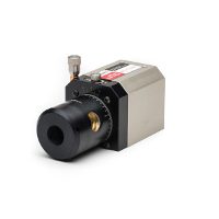
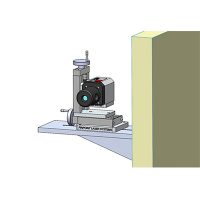
Pinpoint Laser Systems determined that a Microgage 2D System would be perfect for this application, but with modifications. They also selected a cylindrical Microgage Laser Transmitter for the laser reference beam, which was attached to a custom mounting fixture that could slip into the inner diameter of the fuel transfer tube.
This mount consisted of three contact points, two of which were precisely fixed, and the third was a spring-loaded mechanism that held the laser fixture securely in place.
At the opposite end of the fuel transfer tube, the Microgage Receiver needed to be centered, and a means was needed to detect the laser beam when it was outside of the high precision viewing area.
Pinpoint Laser Systems developed a large area detector, that surrounded the Microgage Receiver, that could pick up the laser reference beam and provide an XY position for the operator. The X/Y measurements were displayed on a graphic screen so that the operator could perform the initial course adjustment of the fuel transfer tube alignment until the laser reference beam landed on the Microgage Receiver.
Once the laser beam reached the Microgage Receiver, the accuracy of the measurement was significantly improved,which allowed for the final fuel tube alignment procedure to be completed.

Industry
Products Used & Links
Microgage 2D with cylindrical laser transmitter. Custom receiver assembly with wide area detectors and display feedback. Custom fixturing for laser transmitter and receiver to fit inside of fuel transfer tube.