How To Measure Flange Flatness
Let’s take a look how our Pinpoint Laser Microgage Flatness Solution can help fit for your flange flatness measurement needs. Our tools have been used on many different machines in the field for a simple, intuitive, common sense approach that will help you achieve quick and accurate results.
Traditional methods for performing geometric checks, such as flatness, involve mechanical or visual systems. Mechanical methods, such as straight edges or levels, can be cumbersome or ill-suited for such large flanges and equipment. Visual systems, such as optical sights, are also time-consuming and highly dependent on operator skill.
Our Pinpoint Laser Kit is well suited for checking flatness. The laser transmitter projects a perfectly straight reference beam, running parallel to the face of the flange. The receiver is then placed at any critical checkpoints. The remote processing unit displays the alignment data in real-time, allowing adjustments to be made on the fly.
Below is more information on how our Pinpoint Laser Alignment Sytems can be used for your flange flatness project as well as a detailed look at the components used.

Overview
For example, let’s say we are measuring heat exchanger flanges up to 180” diameter with the majority in the range of 40” to 60” diameter. The heat exchanger flanges will be in the vertical orientation during measurement. Some of these flanges are magnetic. A laser kit is desired to measure flatness of the flange faces with the ability to print a test report.
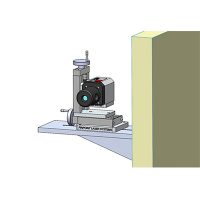
To preform this alignment we recommend our Pinpoint Laser Microgage Flatness System to measure flange flatness (Figure 1) and (Figure 2).
*The Leveler Rotation Mount can be modified by Pinpoint to have magnetic capabilities for quick attachment to magnetic faces. The alignment kit comes standard with a magnetic mount for the laser receiver.*
Flatness: To measure the flatness of a flange face, begin by aligning the laser beam level through 3 points via the fine adjustment knobs on the leveler rotation mount base. The points will ideally be spaced out 120°. This will ensure that the laser beam reference plane is parallel through 3 points on the face of the flange.
When not checking to gravity, the bucking in procedure can be done as before by using the adjustment knobs on the leveler rotation mount to make the angle of the plane parallel through 3 points on the top surface of the gantry rails.
After leveling out the laser, press “zero” on the control unit to zero out the display. Now rotate the laser and move the receiver at any location on the flange. The reading at each location will show + or – how out of flatness each is.
The laser system will have the ability to record these measurements to a data-sheet if desired.

Pinpoint Laser System Flatness System

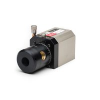
Laser Transmitter
The Microgage Laser Transmitter produces a visible laser reference beam which is used as a datum for the measurements and alignment. The laser is designed so that a collimated beam is aligned to the sides and the base of the laser housing. The laser output beam is typically aligned to 2 arc-seconds or 0.0006 degrees. The laser housing is machined from a solid block of aluminum and anodized to stand up to harsh environments.

Laser Transmitter Microgage Laser Receiver
The Microgage Laser Receiver is housed in a two inch cubed housing. The center of the receiver port and the electronic detector is centered one inch up from the base and one inch from the left and right sides. This receiver measures the position of the laser beam in 2 axis. The receiver is machined from a solid block of aluminum and anodized to stand up to harsh environments.


Microgage 2000/2D/PRO Display
Constructed of hard-anodized aluminum to withstand harsh work environments. Our lineup of adaptable display units reads the X-Y coordinate and has a resolution of up to 0.0001”. Their accuracy is ± 0.0002 inch or 1% of measurement (whichever is greater) and operates at a distance of up to 60’. They have the ability for data transmission to PC or other system. Pinpoint Capture Software is easy to load and use on the computer for selecting and collecting data. The operator can easily set a reading to “zero” by pressing a button. The display can scale measurements, apply offsets, work in millimeters, microns, or inches, or your own units.

Leveler Rotation Mount
This is a precision laser alignment leveling mount to support the laser for measuring and setting flat reference planes. The laser and mount are aligned by several fine adjustment knobs and can be rotated to any position for defining a flat plane. The leveler brake can be attached to a tripod, mounted with fixtures, or simply clamped to a surface. A micrometer brake adjustment is included to lock the leveler and make small angular adjustments.

Magnetic Base Mount
The Magnetic Mount Assembly is a standard component in the Microgage system and ideally suited for supporting the Microgage receiver, 90-Line, and other accessories. The mount also includes a fixed base for added versatility.