Spindle Data Routine
Data analysis and calculations for aligning spindles
How to Align Spindles With the Cylindrical Laser
Step by Step Instructions
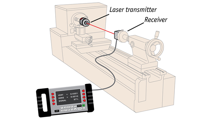
- Set up laser transmitter and receiver at Distance A. (Nearest point on object to be measured).
- Check receiver at Distance B. (Furthest point on object to be measured).
- Un-zero receiver values if activated.
- Clear all data from the Microgage data registers on Capture™.
- Move the receiver to the first measurement position (Distance A).
- Input distance from the front of the laser to the front of the receiver in Annotation Field.
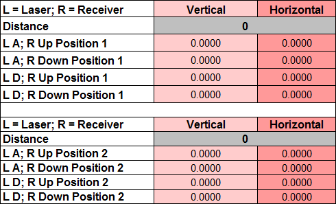
- Make sure that A is up on laser, and label is up on receiver and hit Record Data on spreadsheet.
- Rotate laser so that D is up and hit Record Data on spreadsheet.
- Rotate receiver so that Label is down and hit Record Data on spreadsheet.
- Rotate laser so that A is up and hit Record Data on spreadsheet.
- Move the receiver to the second measurement position (Distance B).
- Repeat steps 6-10 at Distance B.
Typical Spindle Alignment Applications
- Align lathes and turning centers
- Position and adjust opposing spindles
- Align boring equipment
- Monitor and adjust machine tools
- Align bearings and shaft supports
- Align bar feeder
- Plus many other applications


