Challenge
A customer asked Pinpoint Laser Systems to provide a customized laser alignment system that could precisely measure and align the straightness of long rail assemblies used to support the crosshead of a moving gantry.
Two precision rails measuring over 20 feet in length were assembled on the steel frame and needed to be checked for individual straightness and parallelism and flatness. These measurements required an accuracy of better than 0.002 inch (50 micron) and needed to be interactive to provide real time data for the alignment process.
The assembly and alignment process took place in a factory environment and there is also a future need for field service measurements. The customer wanted a system that was easy to use, reliable, precise, and easy to move and transport to locations.


Solution
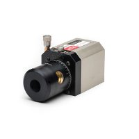
Pinpoint Laser Systems recommended using the Laser Microgage 2D with several standard accessories.
The alignment task was broken down into several specific tasks that could be performed sequentially. The large gantry system is aligned through a series of specific steps. The first involved mounting and aligning the primary guide rail and the Laser Microgauge was an and was an integral part of this process to establish precise straightness in XY axes.
The alignment process involved several iterations because each mounting bolt exerted distortion on the rail so many adjustments are needed along the way as it is tightened. The Laser Micro Gauge proved very useful because measurements can be quickly taken and minor adjustments made to speed the process along. Measurements are taken in a relatively short area, less than 1 m, and then extended measurements over larger lengths to check overall alignment.

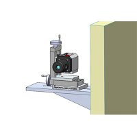
With the first guide rail aligned, a second parallel rail was assembled on the frame and also aligned for straightness in the XY axes. During this process, the laser transmitter was placed on to the Pinpoint Laser System’s Leveler Break, which allows the laser transmitter to swing through a plane and check flatness.
The Laser Microgage made measurements comparing the elevation of the primary guide rail to the second rail to establish a flat plane between the two. From there, adjustments were made to the second rail ensuring that it is straight in the XY axes and also in plane with the primary guide rail.
Checking parallelism between the two rails, was established by projecting the laser reference beam right down the center of the gantry assembly. Measurements could then be made off the primary guide rail and the secondary guide rail for checking parallelism. As the mounting bolts for each rail are tightened, the rail was moved slightly in the left or right horizontal direction to maintain tight parallelism with the primary guide rail.
With the primary and secondary guide rails in place and aligned for straightness, flatness, and parallelism, the Laser Microgauge was then used to check the squareness of the bridge assembly, that rides on both rails. The laser reference beam was projected along the length of the primary guide rail and aligned so that it was parallel in the X&Y axes to this rail.
Pinpoint Laser System’s 90 Line Right Angle is thenthen placed into the laser beam path and redirects the laser beam at a precise right angle for checking squareness. The 90 Line has an internal pentaprism which maintains a precise right angle beam relationship regardless of the orientation of the 90 Line and its housing.
The pentaprism assembly inside the 90 Line can be rotated so the right-angle beam defines a plane of laser light which is square to the original reference beam. This square plane of laser light can be viewed by the Microgauge Dual Axis Receiver, as it is moved across the gantry bridge to check squareness and straightness of travel and real time alignment adjustments made as needed.
Once the gantry system was fully assembled with tracks, guide rails, and cross bridges aligned, the final alignment can be checked by placing the micro gauge receiver into the tool holder and moving it through a series of controlled motions. As the tool holder is moved through precise motions, the XY measurements can be recorded in real time and check for nonlinearities and alignment errors.