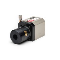
About the Microgage 2D
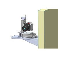
Microgage 2D works on a very simple principle: Laser light travels in a straight line. If you attach a laser transmitter to one assembly and a laser receiver to another, then the alignment of the two assemblies will equal the X/Y displacement of the laser beam at the receiver. And Microgage PRO measures all this with a precision of 0.0001 inch over distances of up to 180 feet.
The Laser Microgage 2D is compact, easy to use, and intuitive. It makes alignments and measuring possible using incredibly high standards and measuring resolutions as precise as 0.0001 inch (2.5 microns) at ranges of 150 feet (45 meters) and longer.
From ocean going vessels to machine shops to aircraft manufacturers, the Microgage 2D is being used in a wide variety of industrial measuring and alignment tasks. Users appreciate the ease of use and the convenience of having two-axis measuring capability andprecise measurements to 0.0001 inch.


Microgage 2D Display Details
- Precise to 0.0001 inches at up to 150 feet
- Easy to set up and use
- Versatile for many projects
- Provides alignment information in real time
- Handles multiple laser receivers
- Battery operated
- Many mounts and fixtures available
- Stores hundreds of readings
- Connects easily to PC for data uploads and analysis
- Easy-grip handle for comfort and portability
- Rugged design for years of industrial use
- Durable carrying case with storage pockets included
- Highly compact and portable
- Virtually maintenance-free
- Requires minimal training
- Free technical support provided
- Assembling long machinery runs
- Measuring stage and slide run-out
- Aligning rolls, idlers and web systems
- Bore alignment
- Adjusting gantry and bridge assemblies
- Aligning gearbox and bearing assemblies
- Verifying rail and track parallelism
- Aligning spindles, lathes and CNC turning systems
- Positioning shafts and transmissions
- Measuring mechanical and shaft defections
- Checking milling and cutting stations
- Adjusting presses, shears and indexers
- Checking injection molding equipment
- Positioning extruder bores and feed screws
- Geometric alignment
- Checking the Z axis on machine tools
- Adjusting x-ray and medical scanners
- Aligning aircraft and helicopter assemblies
- And many other geometric alignment applications
Display configuration – Multi, dual-axis processing system
Receivers – up to 4 simultaneously & expandable
Resolution – 0.0001″ (2.5 micron)
Range – user-configurable
Units – inch, mm, mils, custom
Display – LCD graphic screen 5.0” x 3.0” (127mm x 76mm)
Controls – keypad, multifunction buttons
Info – X/Y & angular data, computations, instructions
Storage – data readings & notes up to 1,000
Housing – solid machined aluminum & hard anodized coating