About the Microgage PRO Plus
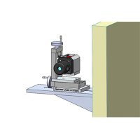
Microgage PRO Plus works on a very simple principle: Laser light travels in a straight line. If you attach a laser transmitter to one assembly and a laser receiver to another, then the alignment of the two assemblies will equal the X/Y displacement of the laser beam at the receiver. And Microgage PRO Plus measures all this with a precision of 0.0001 inch over distances of up to 180 feet.
The Microgage PRO Plus is specifically designed so users can handle virtually any alignment application, with set-up taking only minutes in most cases.
Its rugged and highly portable smart display includes two convenient handgrips, a bright, color touchscreen, a hardware keypad, and a powerful on-board microprocessor that communicates via wires or wirelessly with receivers.
You can use the smart display to view and store alignment measurements, run applications, and upload data to a PC. The smart display can also present step-by-step guides (or “wizards”) for completing complex alignment tasks.


Microgage PRO Smart Display Details
- Precise to 0.0001 inches at up to 180 feet
- Easy to set up and use
- Versatile for many projects
- Provides alignment information in real time
- Wireless option for convenience and range
- Handles multiple laser receivers
- Smart display with bright, easy-to-read color screen
- Touchscreen and keypad with multifunction buttons
- Battery operated (rechargeable)
- Many mounts and fxtures available
- On-screen, step-by-step alignment instructions
- Stores thousands of readings
- Connects easily to PC for data uploads and analysis
- Easy-grip handle for comfort and portability
- Rugged design for years of industrial use
- Durable carrying case with storage pockets included
- Highly compact and portable
- Easy-to-add software updates and user-specifc applications
- Virtually maintenance-free
- Requires minimal training
- Free technical support provided
- Assembling long machinery runs
- Measuring stage and slide run-out
- Aligning rolls, idlers and web systems
- Bore alignment
- Adjusting gantry and bridge assemblies
- Aligning gearbox and bearing assemblies
- Verifying rail and track parallelism
- Aligning spindles, lathes and CNC turning systems
- Positioning shafts and transmissions
- Measuring mechanical and shaft defections
- Checking milling and cutting stations
- Adjusting presses, shears and indexers
- Checking injection molding equipment
- Positioning extruder bores and feed screws
- Geometric alignment
- Checking the Z axis on machine tools
- Adjusting x-ray and medical scanners
- Aligning aircraft and helicopter assemblies
- And many other geometric alignment applications
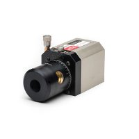
Display configuration – hand-held, portable, self-contained
Receivers – up to 4 simultaneously & expandable
Resolution – 0.0001″ (2.5 micron)
Range – user-confgurable
Units – inch, mm, mils, custom
Display – state-of-the-art, color, high-resolution, touchscreen
Controls – keypad, multifunction buttons, touchscreen
Info – X/Y & angular data, computations, instructions
Storage – data readings & notes up to 10,000
Housing – solid machined aluminum & hard anodized coating