
Pinpoint Capture™ Software
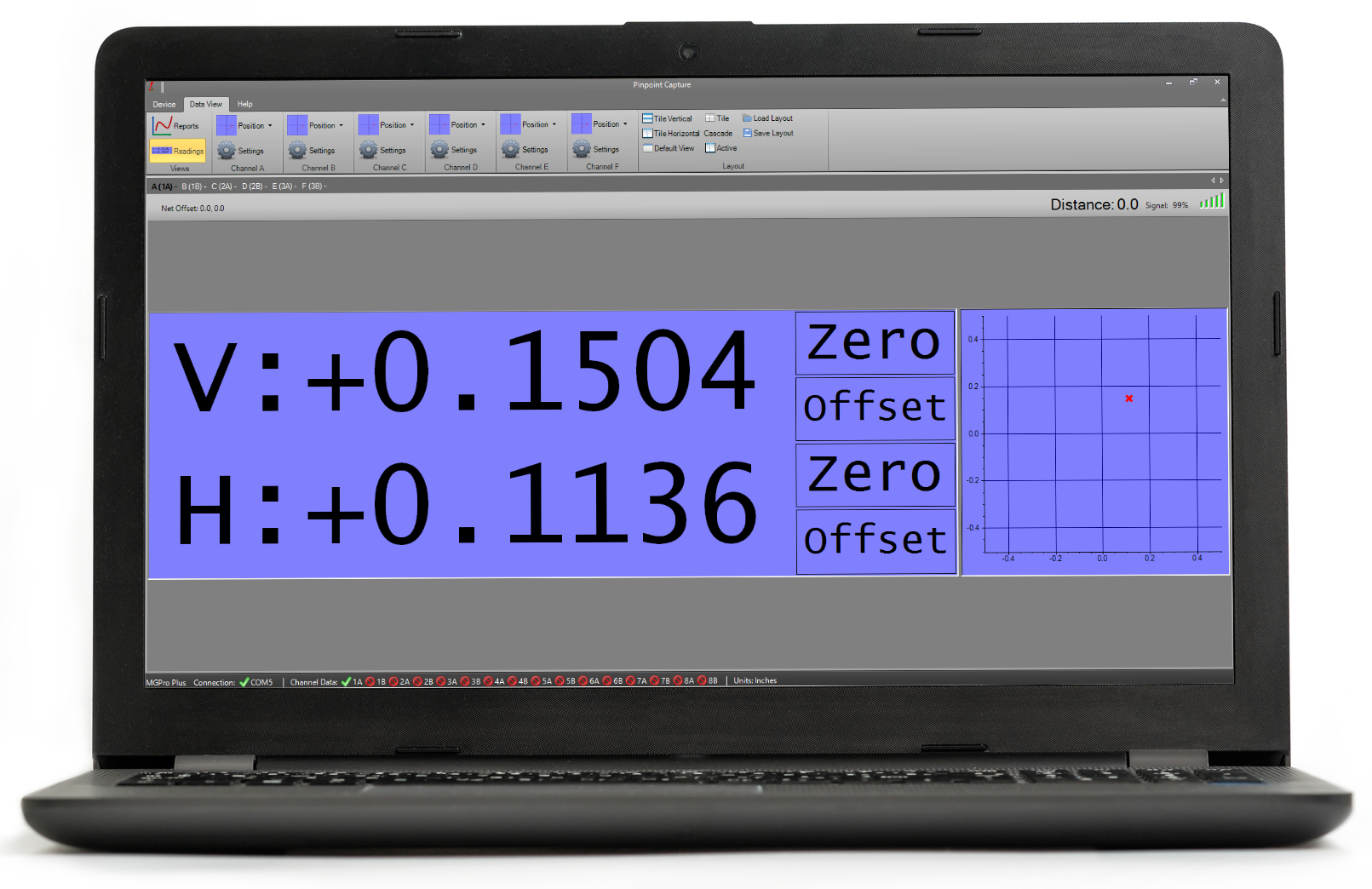
Capture is a Windows-based application, connecting your Pinpoint Microgage system directly to a PC. Watch live readings, record measurements as you move down a machine bed, and capture the results directly into a spreadsheet for analysis and documentation.
Alongside live data readouts, Pinpoint offers application-specific data routines. Each Capture routine is a prepared template that handles the calculations for each alignment application. This includes straightness, flatness, parallelism, squareness, spindle, and bore. Routines are available to all Microgage owners and if you do not see one that matches your application, contact us for more information.
See Capture in use
What the demo covers
- Connecting a Microgage PRO Plus to a laptop and confirming a strong signal
- Setting units, averaging, and precision required for the job
- Assigning receivers to display channels
- Measuring straightness
- Record a reading every four inches with the “Record Helper”
- Reading the finished profile
Live readings on a full-size screen
The Microgage display is easy to read on the instrument, but Capture puts the same readings on your monitor. This allows the user to operate specific Capture routines while easily recording data.
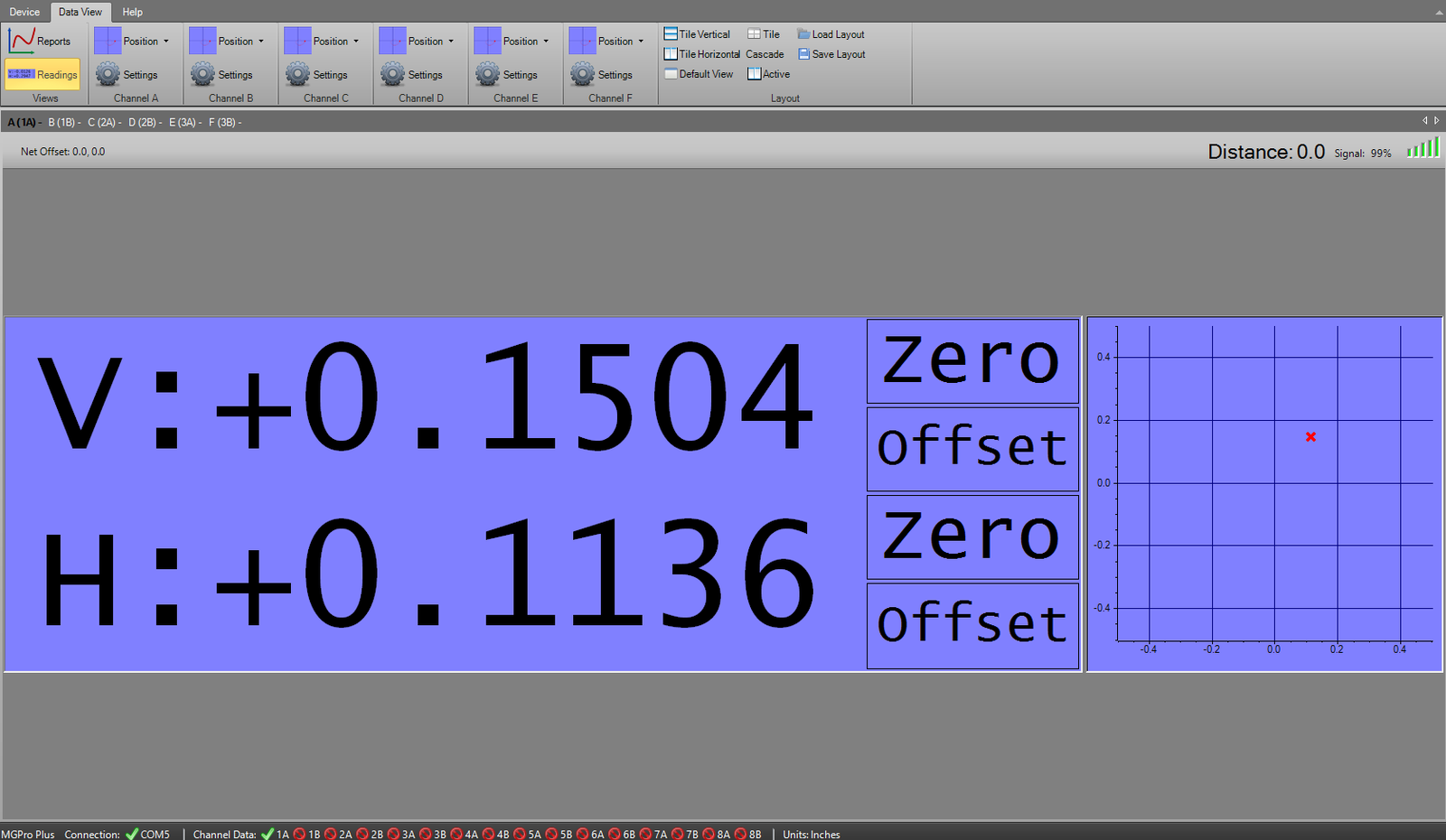
- Vertical and horizontal values shown at a larger size
- Available beam position plot
- Adjust Zero and Offset without changing screens
- Live signal strength always in view
- Set units, scaling, averaging, and precision
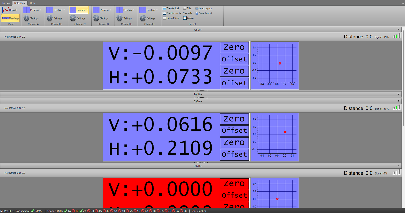
Six channels, arranged how you work
Capture supports six receiver slots. Bring up only the receivers a job needs, add more as the setup grows, and arrange the panels to suit the work. Panels tile vertically or horizontally, cascade, or collapse individually when you want one reading in front of you.
Each channel keeps its own settings, so a job running two receivers on one axis and two on another stays readable instead of turning into a column of numbers.
Check the reading before you record it
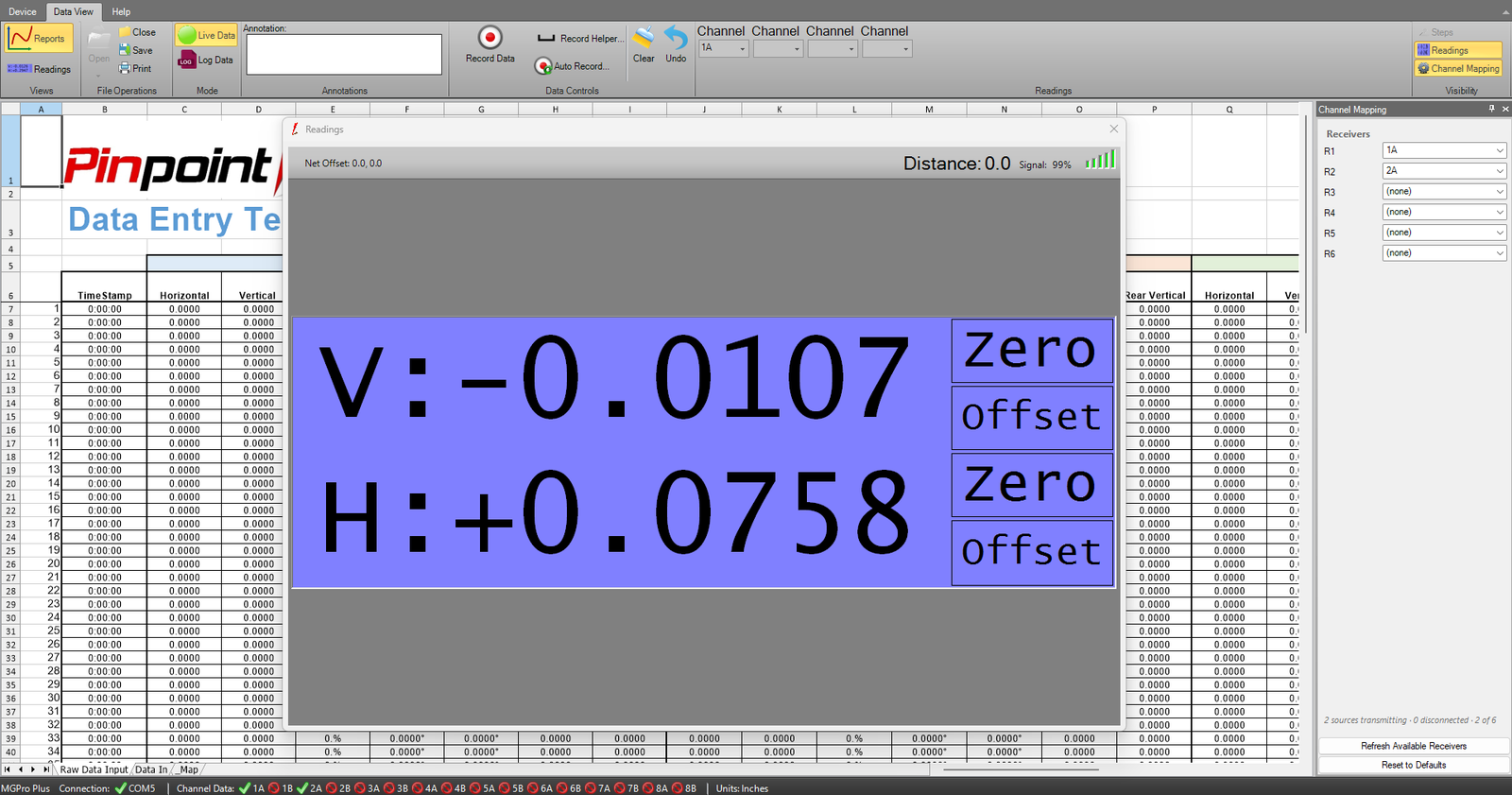
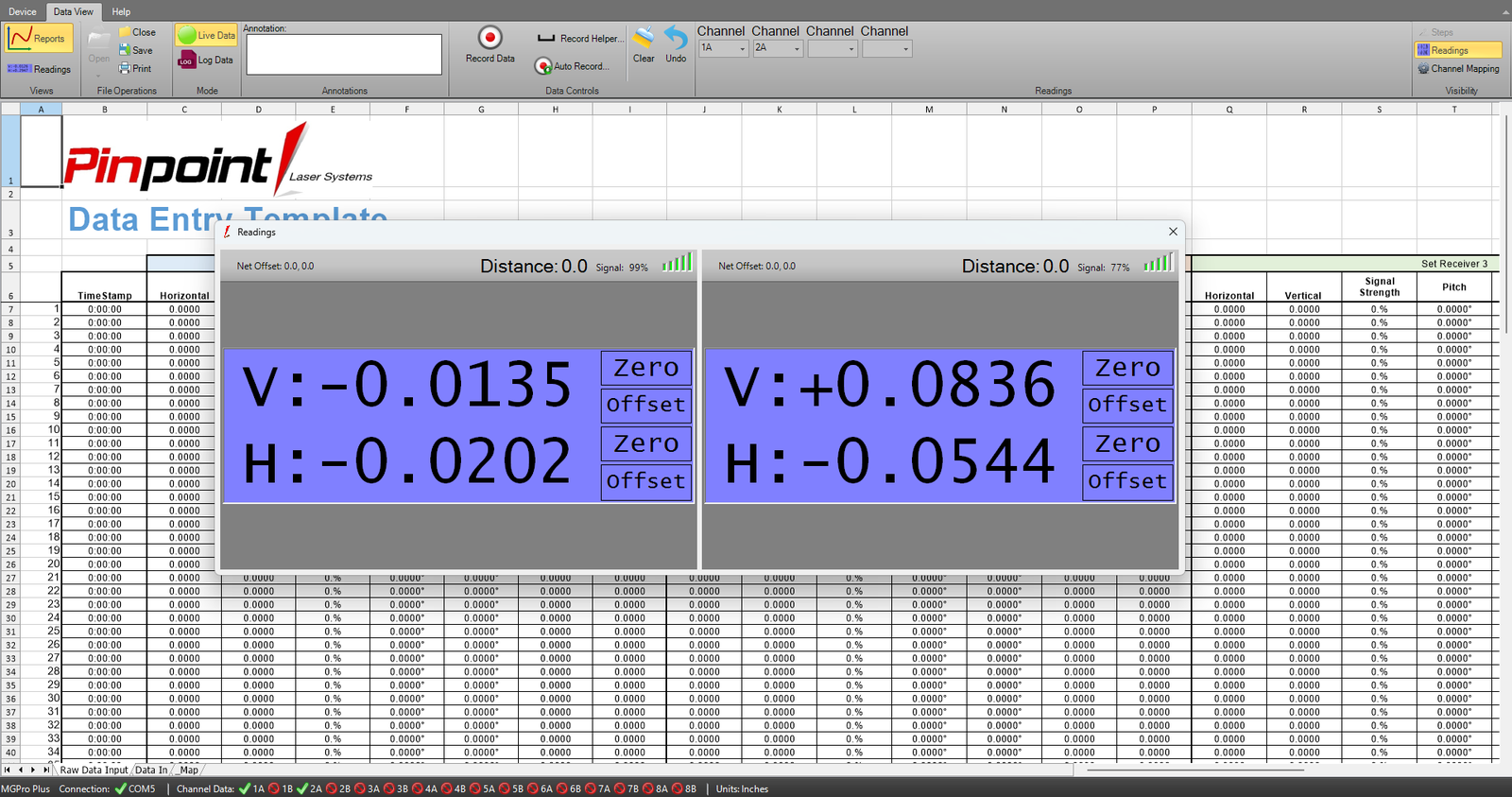
Readings detach into their own window, so you can settle a reading and confirm it is stable before it goes into the routine.
Three ways to record
Match the recording method to the job rather than the other way around.
Record Helper
Move the receiver to the next station and tap the spacebar. Built for stepped measurements where you are taking a reading every few inches down a bed or rail.
Manual with notes
Save a reading when you are ready and attach a note to it, so each entry carries the axis, station or condition it belongs to.
Automatic logging
Set an interval and let Capture log continuously, per second, minute or hour. Useful for watching thermal growth, settling or deflection over time.
Recorded data, reports and completed templates export to Excel for statistics, charting and plotting, or save out as text for import into other applications. Peak to peak error, high and low readings and the rest of your analysis stay in the tools your quality group already uses.
Application data routines
Each routine is a prepared template that collects the readings a given alignment needs and returns the calculated result.
Straightness
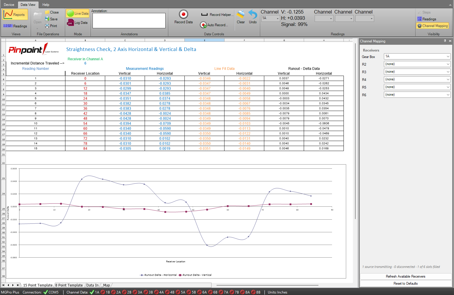
Capture horizontal and vertical measurements on two axes, with line-fit and runout delta values calculated automatically as data is collected and plotted by receiver location. Comes with preconfigured 8-point and 15-point templates.
- Straightness of long machine beds
- Runout on moving slides, tables and stages
- Bend and profile in tracks and guide rails
- Shaft and drive alignment
- Bearings and shaft supports positioned over long runs
- Surface deflection and bending in long structures
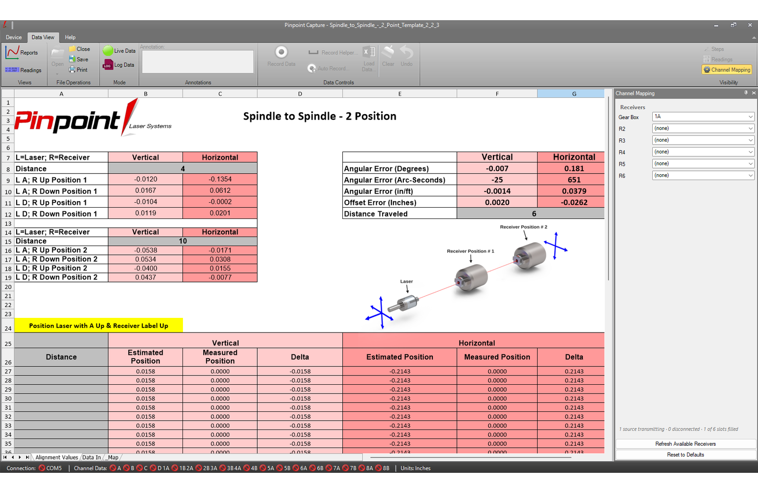
Spindle
Take rotated readings at two positions and the routine calculates and returns angular error in degrees, arc-seconds, and inches per foot, along with offset error in both vertical and horizontal planes.
- Checking and aligning lathes and turning centers
- Positioning and adjusting opposing spindles
- Measuring alignment of boring mills
- Positioning and adjusting precision bar feeders
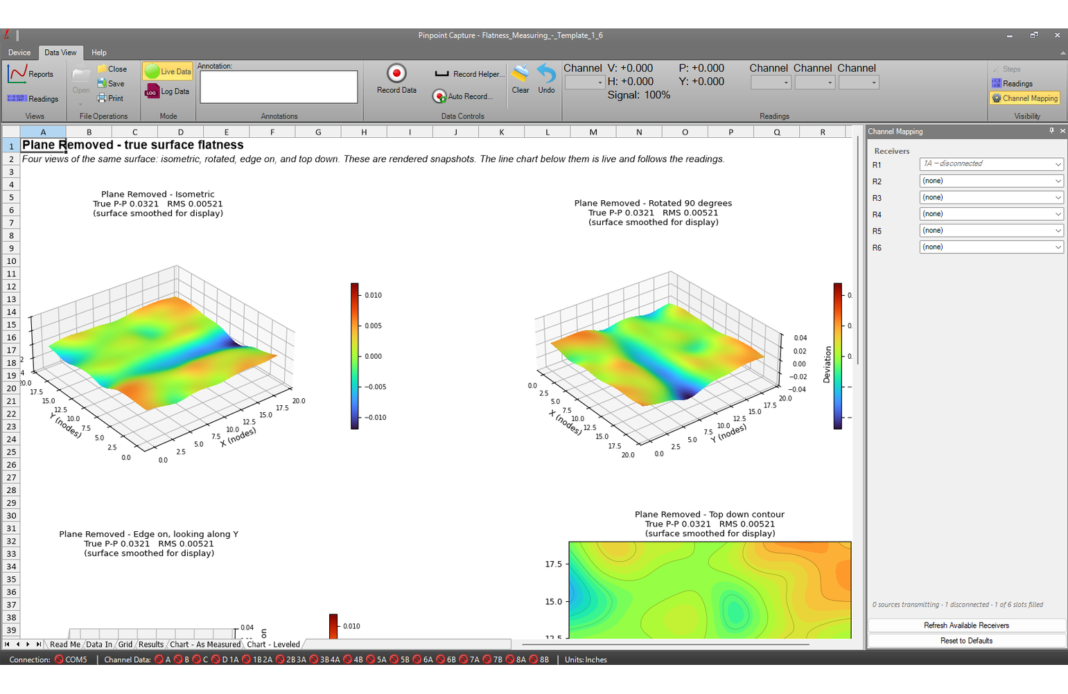
Flatness
Take readings across a surface grid, and the software automatically builds a complete surface profile. A best-fit plane is removed to eliminate any laser setup tilt, isolating the true high and low spots of the surface. Results are reports as Peak-to-Valley and RMS values, making it easy to compare the surface against specified tolerances.
The surface is displayed in multiple views, including isometric, rotated, edge-on, and top-down contour maps, allowing dips, twists, crowns, and other surface irregularities to be quick identified before the component is returned to service.
- Machine beds and work tables
- Surface and assembly profiling
- Flanges and circular planes
- Gantry runout
- Roller and web systems
Additional routines available on request
These routines are ready to go and are provided by our support team when your application calls for them.
- Parallelism, for rollers and web handling, precision tracks, gantry slides and unwind and take up sections
- Squareness and perpendicularity, for machine guides, Z axis and cross bridges
- Bore alignment, for propeller shafts, rudder posts, press rams and extrusion screws
- Custom routines built around your specific alignment
Connecting to your system
Wired on any system, wireless on the PRO Plus
Any Pinpoint alignment system connects to a Windows PC over USB using a DCU cable. The Microgage PRO Plus can also run wirelessly with the Pinpoint USB antenna, which frees the laptop from the instrument when the receiver is working its way down a long bed.

| Operating system | Windows 7 and later, 32-bit and 64-bit |
|---|---|
| Wired connection | USB, using a DCU cable, on any Pinpoint alignment system |
| Wireless connection | Pinpoint USB antenna, Microgage PRO Plus only |
| Receiver channels | Up to six |
| Delivery | Web download or USB drive supplied with your alignment system |
| Data export | Excel, plus text files for other applications |
Not sure which routine fits your alignment?
Describe the machine and what you are trying to hold, and one of our alignment engineers will tell you which routine applies, or build one around your application. Software, routines and updates are handled directly by our support team.
Let's Connect
Phone: (978) 532-8001
Toll-free: (800) 757-5383
Fax: (978) 532-8002
Email: info@pinpointlaser.com
56 Pulaski Street Peabody, MA 01960 U.S.A.