Microgage Alignment For Dual Barrel Extruders

Background
Plastic extrusion equipment works more efficiently and produces better quality parts when it is properly aligned. Frequently, we hear from customers voicing concerns about extruders having the barrel or barrels not in alignment with the screw or the gearbox resulting in poor product quality and, more importantly, damage expensive machine components and rapid wear. Often times, the machine screw is not properly aligned to the extruder barrel causing extensive damage to both.
Proper alignment of extruder equipment is easy to perform and improves manufacturing efficiency, better product quality and profits. The following application note describes how to use a Pinpoint Laser Microgage system to quickly and precisely evaluate the alignment of your extruder system. This information can then be easily applied to re-aligning the machine itself or developing a premature maintenance schedule.
Offset or Centerline Misalignment
Offset or concentricity misalignments occur when the centerline of the rotating gearbox shaft and screw to the barrel are displaced from one another. Offset misalignments fall into 2 axes, typically referred to as vertical or horizontal. These centerline or offset errors tend to be fixed and maintain a constant error value relative to the centerline of the extruder barrel.
Pinpoint builds a variety of laser alignment systems for different applications and machinery configurations. These systems provide better measuring accuracy and are easier to use than many conventional alignment devices or methods. This note and the equipment described in it are primarily for aligning dual barrel extruder barrels and is easily adapted to single barrel extruders. The equipment is well suited for checking the concentricity or offset and parallelism alignment between tools, work pieces and the machine elements that support them.
This application note will give you a step by step procedure on what equipment is needed, how it should be set-up, the steps for taking readings, a simple procedure for downloading your readings and computing the alignment characteristics of your machinery.
How It Works
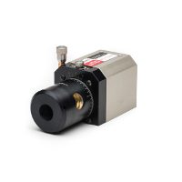
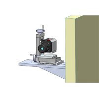
I an typical machine alignment application a self-contained, cylindrical Microgage laser is placed into the machine chuck, spindle or other rotating component of the machine. This laser projects a focused beam that extends the centerline of the chuck or spindle down the length of the machine. A Microgage receiver is secured into an opposing spindle, attached to a moving tool holder, or similar machine feature and detects the laser light position. As the chuck with the attached laser is turned and/or the tool holder or opposing spindle moved the relative position of the laser beam to the Microgage receiver will change if misalignments are present. The receiver is connected to a Microgage display and precise readings are given as parts of the machine are turned and moved. Readings are recorded manually or with a laptop and Pinpoint’s Capture software and calculations can be made to determine runout, concentricity errors, offsets, parallelism errors and other valuable information to diagnose machines and bring them back into alignment.

Measuring Procedure
First, the Microgage Cylindrical Laser is placed into a custom mount that is designed to hold the laser to the gear box shaft, so that the laser beam can project along the axis of its rotation. It is important to note that the laser beam will not be perfectly centered or parallel to the axis of rotation and may appear to be off the center of the barrel centerline, which is normal.

The Microgage Cylindrical Laser uses a mounting flange, shank, or coupling of a precise dimension that is held in the mount. The laser beam then travels some distance down the length of the barrel before it reaches the Microgage Receiver. If the mount does not grip the laser shank evenly or if there is any reason that the laser doesn’t sit squarely in its mounting position, the errors will be exaggerated over the run of the laser beam. For example, if a burr or a piece of debris, such as a metal chip, acts like a shim and the back end of the laser shank is moved off center by 0.005 inch the laser beam will be deflected off the rotational centerline. So, a 0.005 inch deflection acting over a 3 inch shank would translate to a 0.100 inch beam deflection at a laser distance of 60 inches (0.005” / 3” = 0.100” / 60”).
Considering the example above, if the gear mount holding the laser is manually rotated, the laser beam at 60 inches will produce a circular path that has a radius of 0.100 inch or a diameter of 0.200 inch. The measurement producers uses averages from the laser reading taken before and after a 1/2 turn of the laser and gearbox shaft.. The alignment procedure will compensate for some of this error, but anything too large may not project into the detection area of the Receiver. The Signal Strength reading on the Display can be used to monitor this condition. The Signal Strength should maintain a strong percentage (>90%) through the full rotation of the Cylindrical Laser.
Next, the Microgage Receiver is secured into the custom Microgage Cylindrical Mount, which places the Receiver along the centerline of the mount. The mount and Receiver are then placed into the end of the barrel that you are trying to check relative to the centerline of the shaft. Custom size mounts can be provided to accommodate the barrel sizes. The mount has 3 precision contacting points spaced evenly around the circumference of the barrel mount. Two of the contact points or tooling balls are fixed and one is adjustable or spring loaded. (Mounts with four contact points are also availble) The spring loaded ball is set by the factory, but can be easily adjusted by the User. It is important to insure the mount seats firmly in the end of the barrel.

Making the Measurements
By taking a number of measurements with the Microgage Cylindrical Laser and 2D Receiver in various rotational positions, we are able to measure the actual offset error and correct any misalignments.
To begin, manually turn the gearbox output shaft so that the position “A” marking on the laser is pointing up. This will be the starting point of your measurements. You should somehow mark with a pencil, marker, piece of tape, etc. a point where a turning part of the output shaft is in relation to a fixed point of the gearbox. This will help to insure you can return to position “A” after you rotate the laser. When you turn the output shaft precisely ½ turn (180 degrees) to position “D” marked on the laser, this will become your second point of your rotational positions for taking measurements at the gearbox. You should also be careful to mark this position as well. During the measurement run you do not want to move the laser in the mount because this will disrupt the consistency of your readings and alignment measurements.
At the receiver, you will position the receiver with the blue Pinpoint label facing up for one set of measurements and ½ turn (180 degrees) with the label facing down for the second set of readings. You are now ready to start recording your measurements.
The chart below shows the orientation of the laser transmitter and the receiver for each measurement. Move one element (laser or receiver) at a time and take your measurement. For each position, you want to record both the vertical (Vert.) and the horizontal (Horz.) values being careful to note the sign of the measurement, e.g. + (positive) or – (negative). Readings can be recorded manually on paper or saved directly into the Microgage Display unit. These readings can then be manually entered into the Excel spreadsheet or uploaded from the Display unit using pinpoint capture and imported into the spreadsheet.
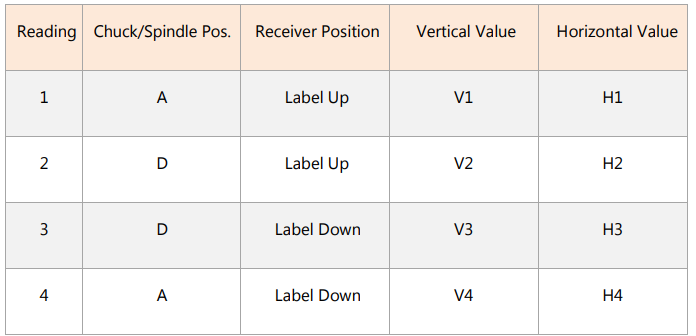
Now, simply add the 4 Vertical Values and divide by 4 for the Vertical offset error:
(V1 + V2 + V3 + V4) / 4
And, do the same for the Horizontal Values:
(H1 + H2 + H3 + H4)/4
You should now know the direction and amount of adjustment needed to align to centerline.
It may be necessary to repeat the measurements especially if you are looking for very small tolerances.
If you have questions or ideas about this or other alignment procedures, please call our Engineering Support team at (800) 757-5383
If you would like to download this whitepaper please fill out the form below
Proper alignment of plastic extrusion equipment enhances efficiency, product quality, and reduces wear on components. Misalignment between the extruder screw, gearbox, and barrel can cause damage. Using a Pinpoint Laser Microgage system allows precise alignment evaluation, improving machine performance and reducing costly repairs. Misalignments such as offset or concentricity errors can be detected and corrected through a step-by-step process involving precise measurements, ensuring optimal operation.