Helpful Tips for Helicopter Alignment
Laser Alignment System for Helicopter Tail Rotor Drive Shafts
Traditional helicopter alignment of the tail rotor shaft involves removing the tail boom assembly from the aircraft and performing the alignment. Traditionally a flat plate is secured to the end of the tail boom, where it formally attached to the helicopter, and piano wire is attached to the plate and lead aft. The wire passes through the alignment fixture that represents the 42 degree gear box and on the way through is directed around a precisely placed pivot point before exiting this fixture. The wire then passes up to a mounting plate for securing the tail rotor gearbox and is secured to a point on a fixture plate. Alignment begins by moving the 42o gearbox fixture until the safety wire passes cleanly through a set of guide holes on each side of the wire pivot point. The 42o gearbox fixture is in alignment when the wires pass cleanly through the holes without touching the edges so that the wire can be strummed and freely vibrates between the tail rotor gearbox and the 42 degree gearbox as well as between the 42o drive gearbox and the forward plate securing the wire. Once the 42o gearbox is correctly positioned the bearing support hangers for the drive shaft sections and their Thompson bearings are positioned so that they are at the correct centerline position and perpendicular to the wire axis. Shims are added left and right as well as fore and aft to position these hangers. The process is repeated for each hanger location. Once complete, the shafts should be able to drop right into place for sound alignment.
Drawbacks to this approach include a time-consuming and tedious process of aligning the reference wire. Aligning each bearing stand using a wire passing through a small hole is subjective and depends upon the user’s eyesight and can lead to many errors. Wire that has been bent or has imperfections can provide different alignment results. The process often involves several people and is time-consuming and if the wire is damaged or broken the procedure must start again.

Traditionally the key aspects of the taught wire alignment include, but may not be limited to the following;
- Two wire endpoints serve as datums and guide the position of the 42o gearbox,
- The forward wire endpoint is positioned precisely in X and Y on a plate,
- The aft wire endpoint is positioned in X and Y on a Tail Rotor gearbox plate,
- The 42o gearbox is aligned for both perpendicularity and centerline to the wire, from the front plate and to the wire running up to the tail rotor gearbox,
- The shaft hangers are aligned for centerline and perpendicularity to the wire,
- Mounting holes and locations are fixed, shims are used for final positioning,
- Once alignment is complete, the shafts can be theoretically dropped into place and secured
Pinpoint Laser Alignment Solution:
Pinpoint laser systems has several solutions to improve the alignment accuracy, repeatability and simplify the tail rotor drive shaft alignment task.
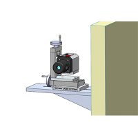
The laser solution begins by replacing the wire with a laser beam and substituting a digital laser receiver in place of the small bushings and wire passages used on each fixture. The laser transmitter is mounted on the plate that is attached to the tail boom when it is removed from the helicopter. If the tail rotor driveshaft system was to be aligned with the tail boom in place, the laser could be attached to the drive flange on the main gearbox. In either case, the laser reference beam points back, following the path of the wire if it were used, to the position where the 42o gearbox is located.

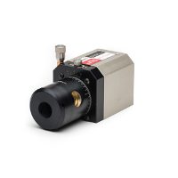
The digital laser receiver for this alignment application is modified so that the measurement readings include the X and Y positions (left/right and up/down) as well as the angular pitch and yaw measurements. These measurements are achieved by placing two dual axis detectors (#1 and #2) in the receiver housing and splitting the laser through a beamsplitter cube so that the beam falls onto both detectors simultaneously. If the receiver housing is parallel to the incoming laser beam, translations to the left and right as well as up and down will show up equally on each detector (Beams A, B and C). If the laser receiver housing is not parallel to the incoming laser beam (Beam 1) the two detector readings will not move equally and their difference is used to calculate the pitch and yaw error numerically. This receiver provides a measuring sensitivity of 0.0001 inch in X and Y and degree (18 arc-seconds) in the pitch and yaw axes.


The 42o gearbox alignment fixture has a mount for the laser receiver. Inside the 42o alignment fixture, there is a mirror, embedded on a hinged assembly that swings precisely 21 degrees against a stop block. When the mirror is swung into position, the incoming laser beam is deflected up and toward the tail rotor gearbox mounting plate. The alignment process begins with the positioning of the 42o gearbox fixture so it is on the centerline and perpendicular to the incoming laser beam from the front plate or the main gear box. By knowing the separation distance between the mounting points of the 42o gearbox fixture the alignment system calculates the shims required for each mounting location. This is a simple spreadsheet operation, easily done on a laptop or performed in embedded software on the Microgage smart display.
In order to set the forward and aft position of the 42o gearbox the mirror is flipped up against its stop so the laser is reflected to the tail rotor gearbox. A dual axis receiver is placed on the rotating gear box flange and as the 42o gearbox fixture is moved forward and aft the laser beam sweeps up or back across the receiver up at the tail rotor gearbox. The forward and aft 42o gearbox position is complete when this upper receiver reads 0.000. As a side note, you can also place the receiver that measures X, Y, Pitch and Yaw up at the tail rotor gear box location and make sure that the beam coming in is centered and perpendicular to this reference surface.
Once the 42o gearbox is positioned and aligned you move on to aligning the shaft supports and hangers for the shaft couplings. The receiver has a simple adapter coupling so that it can sit right in the bearing support and catch the laser reference beam coming from the front plate at the forward end of the tail boom. The receiver provides information on the centerline position as well as any angular misalignment for the bearing support to the incoming laser reference beam. Once again, knowing the separation distance of the 4 mounting points for each bearing support, a quick calculation is made showing the exact combination of shims required to properly align that support. The shims are then put into place and the receiver placed back on the shaft support for a final check. Readings of 0.000 in the X and Y axes and for pitch and yaw ensure the bearing support will position the shaft on the correct centerline and perpendicular to the axis of the shaft. This process would be repeated for each hanger bearing or shaft support until they are all aligned on the common centerline and perpendicular to the laser beam.
In this way, you would be able to align the 42o gearbox so that it is on the centerline and perpendicular to the incoming laser beam while at the same time checking its alignment to the reference plate up on the tail rotor shaft gearbox mounting. The alignment of each shaft support and the calculation of what shims are required is performed at each support location.
With some slight modifications to the fixturing, it is possible to check the alignment of the shaft hangers and the 42o gearbox without actually removing the tail boom from the helicopter. Another option is for the laser transmitter to be mounted on the main gear box and the laser reference beam projected through the tube under the engine and back to the 42o gearbox. By removing the shaft sections and placing the receiver on the shaft supports and the 42o gearbox you could check their alignment position and perpendicularity.

Components Needed for the Drive Shaft Alignment;
- Laser Transmitter & mount for the end plate at the forward end of the tail boom, or on the main gear box drive flange
- Microgage 4D, 4 Axis Receiver (X, Y, Pitch & Yaw)
- 42o gearbox fixture with hinged mirror block & receiver mounting,
- Tail Rotor Gearbox Mounting Plate and Dual Axis Receiver,
- Adapter mount for placing the 4 Axis Receiver in each bearing support,
- Spreadsheet or software for calculating shims and placement
If you would like to download this whitepaper please fill out the form below
Traditional helicopter tail rotor shaft alignment uses a wire and guide system, which is time-consuming and prone to errors. Pinpoint’s laser alignment system replaces the wire with a laser, improving accuracy and ease by using digital receivers for precise X, Y, pitch, and yaw measurements.