Helpful Tips: Tail Rotor Shaft Alignment
Laser Alignment System for Tail Rotor Shafts
In 2003 Pinpoint Laser Systems®, Inc., began development work on a system to improve the alignment of tail rotor drive shafts on Sea King helicopters. Pinpoint was approached by
a customer in Canada that was very familiar with the Sea King Helicopter and had experimented with different ideas for simplifying the difficult shaft alignment procedure for the four shaft sections between the Main Gear Box (MGB) and the Intermediary Gearbox (IGB). Other laser solutions had been attempted but lacked the needed precision, and most importantly were unable to make measurements over distances of more than a few feet.
There are several problems with the traditional shaft alignment technique that involves the
use of string or wire:
- String process is time consuming requiring 4 to 7 people work for 5-7 days
- String process has accuracy limits, best results are about 0.1 inch or 2.5 mm
- Process is trial and error and a high degree of skill & patience are required
- When the shafts are installed, it is difficult to check the work
Pinpoint’s experience with precision laser and alignment systems that operate over long distances and deliver high precision measuring and alignment capability provide a solid fit for this project. Working closely with GasTOPS, Ltd., Pinpoint adapted one of its standard
measuring systems, called the Microgage 2D, to fit onto the Sea King and essentially replace the conventional string and wire alignment method with laser light.
The first system was delivered in February of 2003 to the Shearwater Military Facility in Dartmouth, Nova Scotia, Canada, and run through an extensive trial and evaluation process. Lessons learned from this testing were helpful in making modifications and improving the system’s ease of use. By June of 2003, approximately six months after the first design meeting, the laser alignment system had been improved upon and was returned to the customer and put into additional testing trials and regular use.
Over the last three years, this Sea King Laser Alignment system has been tested and evaluated extensively by the Canadian Military Forces. Additional systems have been purchased and are in regular use in Nova Scotia and British Columbia. The laser system has been used successfully to align Sea King tail rotor shafts in the Persian Gulf theater in May of 2003 and more recent alignments on the deck of a destroyer in the North Sea in February of 2005.
Product improvements and advances continue and this Laser Alignment system has proven to save time and significantly improve the shaft alignment accuracy on the Sea King. Present alignment results include:
- Shaft replacement and alignments are completed in 1 to 3 days
- Alignment accuracy is < 0.010 inch 0.25 mm over the complete shaft run,
- The digital precision of the laser system gives direct feedback for adjustment
- Personnel find the laser system easy and quick to use
- Shafts can be measured and checked quickly right in place
Sea King Laser Alignment System Benefits
- Shaft Alignment resolution of 0.001” or 0.025 mm
- Shaft alignment accuracy for 4 drive shafts to < 0.010 inch or 0.25 mm
- Four Sea King shafts can be replaced & aligned in 2 days with 2 or 3 people
- Alignment data is digital so you know how far and which way to move shaft
- Shafts can be checked quickly in place for misalignment
- Alignment results are quantitative and can be recorded and documented
- Errors associated with swinging or sagging wire are eliminated
This Laser Alignment system delivers a number of unique benefits for tail rotor shaft alignment;
ENTER GRID
The information in this bulletin shows the capabilities of the Sea King Laser Alignment system and further illustrates the components of the system and its various features. Improvements are being continually made and our engineering staff is very comfortable making modifications to this system to meet your particular needs and requirements.
For further information or questions please contact us:
Technical Overview
The Laser Alignment Solution
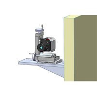
The wires or strings used in traditional shaft alignment procedure are replaced with two beams of laser light. The laser transmitters are mounted to the gust plate on the Intermediary Gear Box (IGB) at the end of the tail boom as shown in the drawing below.

The lasers project forward to a pair of digital receivers mounted on a plate that is attached to the tail rotor drive flange coming off the Main Gear Box (MGB). The laser mount has precision adjustments so that each laser beam can be moved to the exact center of its receiver on the MGB. The display, which is not shown, has a pair of digital readouts that show the position of the laser vertically and horizontally – when these readings are 0 the laser beam is centered in the receiver.
A shaft adjustment receiver is then secured to the shaft being adjusted and the display shows the position of this shaft relative to the centerline of the two laser beams. Adjustments are made left and right as well as up and down until the shaft is in its final position.
Traditionally, two wedges have been used to elevate and move the shaft section requiring a careful approach and many trial and error attempts to achieve alignment. Pinpoint developed an adjustable shaft support that uses finely threaded adjustment screws to move the shaft into final alignment position. The shaft sections can be adjusted precisely and quickly to their correct position and the shaft couplings mounted in their proper orientation.
Components
Components Tail Rotor Shaft Alignment System
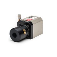
Laser Syterm – IGB Fixture

- 2 Laser Beams
- Attached to IGB
- X-Y Adjustment
- Easy to Adjust
- Battery Powered
Laser Placed at IGB

Receiver is Endpoint at MBG

- MGB Fixture attaches to Main Gear Box
- Sea King has little space in this area
- Lasers are adjusted to zero in X and Y at this point
- Alignment is checked periodically
Receiver is Endpoint at MGB

Shaft Sections Positioned with Receiver