Tube, Shaft and Pipe Laser Measuring System
Overview
The following document describes a measuring system that can be used on the factory floor for checking multiple parts to ensure that the parts are within specification when compared to a known standard part. This process will determine if the centerline alignment of the test part ends are within defined manufacturing tolerance to the tube body. A correct part has each end on a common centerline to within 0.008 inches.
The measurement system needs to be ruggedized for demanding industrial use and also precise enough to make critical measurements on an ongoing basis. In addition to placing and removing parts for testing, the operator should be given a visual indicator, signaled by a green, yellow, or red data background to indicate a passing or failed part. Measurement readings would also be retained for later analysis and printing.
Pinpoint Tube, Shaft & Pipe Measuring System
The measuring system incorporates Pinpoint’s Laser Microgage 2D measuring and alignment system with a mounting and table system to support the object being tested. The system includes the following key items, shown in the illustration below:
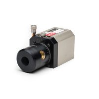
1) Laser transmitter producing a laser reference beam for measuring.
2) Adjustable test stand and toggle clamps to hold various sizes of test parts.
3) Two Microgage digital laser receivers, placed in the ends of the part being checked.
4) Microgage 2D Display Unit for processing and generating data.
5) Slide out Laptop drawer running Pinpoint Capture software to present and save results.
6) Mounting table and storage for computer, power, calibration standard, etc.
7) Optional Monitor

Measurement Procedure
For routine operation, the object is placed into the V-block mounts and clamped into place with four toggle clamps. The Pinpoint Microgage transparent digital receiver is inserted into the forward end of the part being tested. This receiver measures in X-Y axes to a precision of 0.0002 inch and also allows the laser reference beam to pass cleanly through the part. A second receiver is inserted in the back end and also provides an X-Y measurement. The two receivers are connected to the Microgage display unit which calculates measurement values and provides a USB interface to a computer running Pinpoint’s Capture program. The forward and back measurement readings are compared and presented on an adjustable monitor for the operator to observe. If the readings fall within a prescribed tolerance, the screen displays a green indicator. If the parts fall outside of a defined tolerance the values are noted with the yellow or red background. Readings for each tested part can be saved in an Excel spreadsheet and is available for printing and saving.

We anticipate that a part can be placed onto the test fixture and measured, with data collection, and a pass-fail indication in approximately 20 to 30 seconds, depending on the size and complexity of the test part. In addition to a normal operating mode, this measuring system can be configured for different size parts and is also easily calibrated to a known standard for comparison measurements.
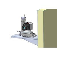
A Pinpoint Microgage laser transmitter is positioned at the left end of the test assembly and projects a precise reference beam used for the measurement process. Laser transmitter is shown mounted on Pinpoint’s 4 Axis Precision Mount which allows for vertical and horizontal linear motion as well as pitch and yaw adjustments. In this way, the laser beam can be adjusted to pass through the center of the test part. If this ability to adjust the laser is not needed or desired, the laser can be mounted on a fixed platform and all of the calibration performed by the display unit and in the software without laser adjustment.

The test stand is adjustable and consists of two aluminum V-blocks that support the test part approximately 12 inches above the table surface. This allows for the part to be turned through a full rotation without the arm or flange contacting the table surface. The V-blocks can be moved close together for small parts or spread apart to accommodate larger test items. These V-block assemblies are secured firmly to the table with 3/8-16 lockdown screws equipped with handles for tightening and easy release. The available mounting hole pattern, not shown in these illustrations, allows for V-block positioning in 1-inch increments to accommodate various break assembly parts. The V-block feature on top allows the break assembly part to repeatedly settle into a known position for the measurement and four locking mechanisms secure the break assembly in place. When the break assembly part is secured in the V-block mounting, the laser reference beam will pass through the approximate center of the part.
The measurement of each test part position is accomplished with a pair of Pinpoint Microgage receivers which are inserted into each end of the part and provide a high precision measurement. The measurement is made, at each location, in the vertical and horizontal axes to a precision of 0.0002 inch. A Pinpoint Microgage Transparent Receiver is placed into the collar, closest to the laser, so that the X-Y measurement can be made and also allowing the reference beam to pass cleanly through the part for the second measurement.

The transparent receiver is attached to a modified Pinpoint bore assembly that allows for reliable registration inside the collar assembly as well as easy insertion and removal. The end of the receiver is equipped with two precision tooling balls that register on the inside surface of the tube end. Opposing these two contact points are two spring-loaded ball plungers with hardened steel contacts that press the receiver assembly against the collar’s inside walls for the measurement. The illustration shows a single pair of tooling ball contacts and opposing spring loaded ball plungers – we may collectively decide to double this mounting configuration, with two pairs of contacting reference points for better support.
The second receiver measures the X-Y position of the collar at the far end of the test part. This receiver also relies on a pair of tooling balls and spring-loaded ball plungers to secure the receiver inside the tube end allowing for insertion and removal on a repeatable basis. Both receivers have a heavily reinforced cable connection to the Microgage 2D Display and these cables have been left out of the illustrations for clarity. A quick-access receiver holder, not shown, would be provided to store the two receivers between part changes and when the system is not in use.
Both receivers are connected to the Microgage 2D display and processing unit for calculating the measurement values and providing USB information to a laptop computer running Pinpoint Capture. This display unit can be set up in advance, during the calibration process, and then locked in one of the lower drawers for standard operation. Similarly, the laptop can be located in a drawer and secured. The measuring system would be configured to run on AC power which can accommodate the laser source, processing unit, laptop, and monitor.

Calibration Process
The calibration process would be performed initially, in Calibration-Mode to set up the test system for a specific type of test part. The process would then be switched to Operation-Mode to allow for the continuous measuring of test parts. The first step in the calibration process is to adjust the V-block stands for appropriate spacing to support the test part. Next, a calibration part would be clamped into place and the laser adjusted so that the reference beam passes through the approximate center of the test part. As mentioned previously, this laser adjustment can be left off and calibration can be done completely in software if needed. The forward and rear Microgage receivers are then inserted into the part and a simple save and calculate routine is employed to measure the calibration part and store its baseline readings. These readings will be compared to tested parts for a pass-fail criteria. When the calibration process is complete, the display unit and the laptop can be secured in their storage drawers and the system is ready for continuous part measuring.
Measuring and Part Checking Process
The operator, working on the production floor, simply takes the item to be tested and places it in the V-block assembly. The four locking toggle clamps are then pressed into place securing the test part firmly in the V-block mounting. With the laser turned on, the two receiver assemblies are inserted into the end of the break assembly part. With the two receivers in place, the operator hits a save button and readings from both receivers are recorded and compared in Pinpoint’s Capture program. If the measurement values fall within acceptable limits when compared to the calibration part, the operator receives a green indication on the monitor and the readings are retained. If the measurements on the part fall outside the acceptable limits, the operator would be notified with the yellow or red background on the monitor along with the display of the measurement readings.
")
If measurement data is to be stored, this process can happen in the background and each measurement routine would save the values from both receivers, their combined differences in comparisons to the calibration piece. If tracking individual parts is needed, the software can easily accommodate a notation or part number prior to testing so that serialized results can be saved.
This sample Pinpoint Capture screen shot is an example of how measurement information might be presented.

The measurement readings are live and saving the readings updates a display screen that could be similar to the screen example to the right. The difference in measured end position and centerline values for the horizontal and vertical axes are presented. Those that fall within acceptable limits are highlighted in Green and those outside of the limits might be highlighted for the operator in Yellow or Red.
The operator could have the opportunity to save the readings for a specific designated test part or not save these readings. The readings could also be saved in the background for statistical analysis later on.
Again, Pinpoint’s Capture program is easy to use and with a built in Excel spreadsheet can be easily configured for various templates and engineering needs. W are glad to assist with other ideas and configurations for this information presentation and storage if needed.
Measuring System Specifications
- Measurement Sensitivity 0.0001”
- Measurement Repeatability 0.0005”
- Measurement Accuracy 0.001”
- Laser Wavelength / Power 635 Nm, < 1 mW
- Laser Classification: Class IIIa or Class II as requested.
- Power Requirements: 120 VAC, < 100 watts
- Computer Interface: USB
- Measurement Software: Pinpoint Capture & Excel Sub-routine
If you would like to download this whitepaper please fill out the form below
The Pinpoint Tube, Shaft & Pipe Measuring System uses a 2D Laser Microgage to check part alignment. It features precise measurements with visual pass/fail indicators, data storage for analysis, and is designed for quick, accurate checks of parts on the factory floor.