Machine alignment is critical for precision manufacturing and operational efficiency of many industrial operations. Improper alignment of various machine components such as bores, lathes, motors, drums, couplings, shafts, and rollers can lead to friction, resulting in premature wear, decreased productivity, poor product quality and increased maintenance.
Laser alignment systems offer an automated and precise method for measuring and aligning machines to manufacturing specifications. They also can calculate machine leveling, runout measurement and surface flatness. Proper alignment leads to longer machine runs, reduced wear, consistent product output and decreased energy consumption.
While user-friendly, laser alignment systems must be properly configured to get perfect laser measurements. Composed of a laser transmitter and receiver, proper positioning of the two assemblies and straightness of the laser light are essential in getting precise measurements as small as 0.0001 inch (2.5 microns). Users should also choose the right configuration for their operations and specific measurement requirements.
Here are some tips to get the best laser measurement results.

Properly Distance the Receiver from the Transmitter
Different models of laser alignment systems have varying requirements when it comes to positioning the receiver and transmitter. For example, the Pinpoint Laser Microgage 2D system operates best when the distance between the receiver and the laser is a few inches out to about 180 feet (55 meters) while the Microgage 2000 can go out to 100 feet (30 meters). If the receiver is set too far away, the signal strength will drop. Ensure the signal strength is maintained above 25% at all times. It is typically indicated by the laser alignment system.
Choose the Right Housing for the Laser Transmitter
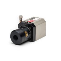
A laser transmitter with a rectangular machine flat housing is recommended for use on fixtures, tripods, and machinery. A round cylindrical laser transmitter is ideal for bore alignment, spindle alignment, shaft alignment, checking lathes and other mechanical alignment applications.
Square the Laser Transmitter to the Front of the Receiver
When squaring the receiver to the incoming beam, check that the direction of the laser beam reflects off the front of the receiver. Positioning the laser transmitter and receiver within 15 feet of each other, adjust either unit until the laser beam reflects off the front of the receiver.
Buck the Laser Beam for Straightness
Ensuring the laser reference beam follows a straight path requires “bucking in” or adjusting the laser beam so it runs in alignment with a surface or machine. If measuring the straightness of a long assembly, the laser is “bucked in” so that readings between two points or reference datums on the assembly are the same value.
Average Measurements to Get Best Readings
Average measurement readings instead of taking absolute values at specific intervals to get more accurate data, especially for applications with interfering variables such as air currents. Using a laser alignment system with averaging capabilities compensates for variables and takes the guesswork and time out of trying to manually conduct calculations. It can average values corresponding to a time in seconds between reading updates for specific applications.


