A lathe is a versatile tool used in manufacturing and machine shops to shape and cut metal, plastics, wood and other materials into intricate shapes and contours. One of the main components of a lathe is the headstock, which contains the motor, spindle, gears and controls. The headstock provides rotational motion and incorporates a chuck or collet that holds the workpiece securely while it is rotated against a tool bit at varying speeds and directions. By ensuring the workpiece remains firmly in place, the chuck maintains the stability and accuracy of the machining process to achieve high-quality shapes and dimensional accuracy in finished machine parts.

Problems with Misalignment
Alignment of the lathe headstock spindle and chuck, relative to the lathe bed, is critical to ensure even cuts and avoid excessive wear on tools. Misalignment can reduce productivity and output. A laser system can quickly and precisely evaluate the alignment of the spindle and chuck, providing information to realign the machine and apply correction factors for the future.
Misalignment Categories
Lathe and spindle misalignment fall into two categories: offset/centerline and parallelism/angular. Offset misalignment occurs when the centerlines of the rotating spindle, chuck or workpiece are displaced from each other in either the vertical or horizontal axis. Parallelism misalignment happens when the axes of rotation and tool movement are not parallel.
Checking Alignment
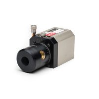
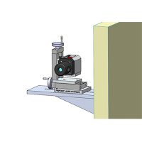
A laser alignment system can check both misalignment types between tools, workpieces and the machine elements that support them. In operation, a transmitter is mounted on the machine chuck, spindle or collet and projects a laser reference beam along the centerline of the lathe to a digital receiver mounted on the tool holder or tailstock of the lathe. A display records readings for alignment.
Making Measurements
Measurements should be taken in various rotational positions and tool locations to determine angular errors.
• Start by manually turning the chuck or spindle to the “home” position and placing a piece of tape labeled “A” on top of the chuck.
• Next, turn the chuck precisely ½ turn (180°) and place a tape labeled “B” on it. These are the two rotational positions for taking measurements of the chuck.
• With the receiver attached to the tailstock, average the two measurement points. For simplicity, the A position is located where the receiver label is facing upwards while the B position is located when the receiver has been turned 180 °and the label is facing downwards.
• Begin recording measurements by moving one element (chuck/spindle position or receiver) at a time.
Calculating Error
The chart below shows the orientation of the laser transmitter and receiver for different measurements. Use recorded values to calculate the total error or misalignment between the spindle or chuck supporting the laser and the mounting point for the receiver. The formula below determines the vertical centerline position:
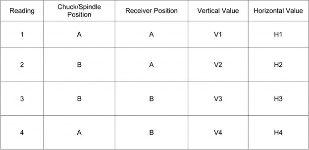
[((H1 + H2) / 2) + ((H3 + H4) / 2))] / 2 = Horizontal Centerline
These results will show the direction and amount of adjustment needed to align to the centerline.
Don’t hope for the best when it comes to proper lathe alignment. A laser alignment system offers better measurement accuracy and is more user-friendly compared to conventional alignment devices to align chucks, spindles and headstock turning equipment.


