Industrial rolls and idlers are utilized in various manufacturing equipment to process material or guide thin films and coated materials along production lines. They are commonly used in printing presses, paper machines, converters, coaters and conveyor systems.
Problems Caused by Roll Misalignment
Roll alignment is crucial to efficient operation of these systems to enhance productivity and high-quality output. Wear, improper adjustment or irregular maintenance can lead to roller misalignment. Misaligned rollers can cause instability, resulting in material tracking errors and damaged product.
In the lamination of substrates where pliable plastic or metallic materials are coated, misaligned rollers can cause materials to wander off the roll centerline, resulting in waste and downtime. Roller misalignment also can stretch material if the edges and center of the roller system have unbalanced paths. While some compliant plastics can spring back, copper foil, metals and Kevlar films can become permanently deformed and unusable.
Lasers Precisely Align Rolls
Laser alignment systems offer a precise and convenient method of checking roller alignment over traditional theodolites, levels and optical inspections. These wireless laser alignment systems can check roll profile and horizontal/vertical alignments.
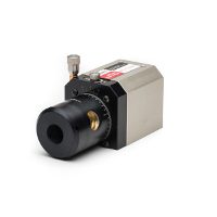
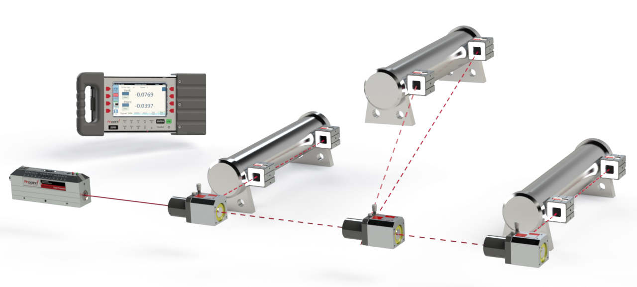
A laser alignment system consists of a transmitter that emits a beam of laser light and a receiver that scans the laser beam, providing a reading of displacement across the horizontal and vertical axes with an accuracy of 0.0001” (3 microns.) Data is displayed digitally on a screen or exported into a laptop.
Profiling Roll Surfaces
The output on the X and Y position of the laser beam can be used to calculate surface flatness, straightness, and parallelism to determine misalignment errors. Roll alignment should be checked for straightness and parallelism in vertical and horizontal directions.
Straightness
Measuring roll straightness can reveal problems with wear, damage, sagging and defection. High deflection can cause sheets of material to follow a shorter or longer path in the middle of the roll rather than the two supported edges of the roller.
A laser alignment system can check the crown or profile of a roller. Consistent readings denote a roller with a straight surface, while a crowned roller will show different readings in the middle and edges.
Roll Parallelism – Horizontal and Vertical Alignment
Roll parallelism is defined in vertical and horizontal planes. To measure vertical orientation, laser light Is directed across the top of the roller and provides a height reading to the left and right side of each roller. The difference shows how it sits relative to the reference plane created by the laser.
By measuring rollers and calculating the difference between readings, a precise and quantitative measurement of parallelism between rolls in the vertical dimension can be obtained.
To measure horizontal alignment, a 90° line is used as a reference plane.
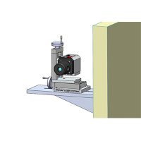
The laser beam is directed along the outside edge of the machine, and a 90° line is introduced into the laser path to redirect the laser across the face of a roller. The difference in readings on each roller at the near and far ends shows its orientation relative to the stationary square laser reference beam. Moving the 90° line along the laser beam path provides a series of parallel laser reference lines for checking each roll.
Manufacturers can use these laser alignment techniques to make precise measurements to ensure roller alignment in different orientations. This helps optimize the efficiency of machine operations while reducing scrap and lost production time.


