Vessels, such as ships, tugboats and yachts and other watercraft, use propellers for propulsion. The propeller transforms the power generated from the main engine, which is connected by a shaft, into a rotational motion to move the vessel.
Proper alignment of the engine and propeller shaft is essential for the efficiency, performance, and operational reliability of the propulsion system. The centerline of the driveshaft and the propeller must be aligned with tight tolerance to prevent shaft wear and water leakage through tight shaft seals, reduce fuel consumption, minimize vibration and avoid structural failures.
Several methods are used in propeller shaft alignment. In some cases, alignment is performed starting from the engine or gearbox, moving towards the stern through the bearing supports, stuffing box or stern tube to the propeller. Typically, shaft alignment is referenced off the fixed stern tube or along with an exterior strut tube.
Benefits of Laser Alignment
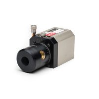
Laser alignment systems adapt easily to different approaches while providing the precision needed for quick adjustments. Unlike traditional methods using wire and indicators, which require manual positioning along a sight line, a laser system projects a thin beam of light to a digital receiver and display for measuring alignment in the X/Y axes. Capable of taking measurements as small as 0.0001”, laser systems offer unmatched precision, efficiency and real-time feedback when making adjustments to propeller shaft alignment.
Using Laser Systems for Alignment
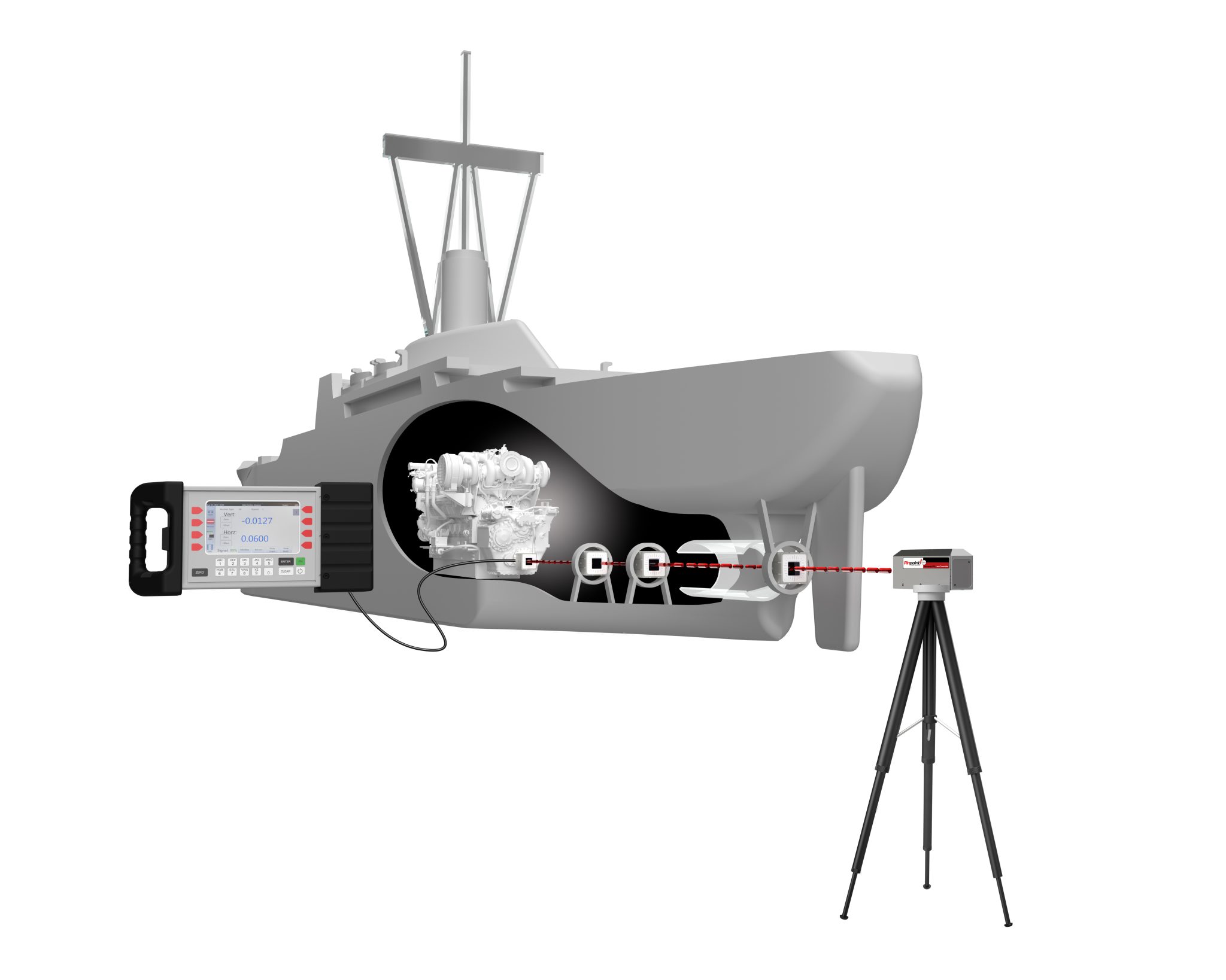
In the forward alignment technique, a laser is mounted near the propeller and projects a laser reference beam that passes through the strut tube or cutlass bearing, stern tube, support bearings and reaches the engine or gearbox. The laser beam can verify the alignment of each component of the propulsion system.
Initially, a visual rough alignment is conducted to position the laser beam as close to the centerline and parallel with the shaft axis as possible, referencing either the stern tube or the cutlass bearings. During the final laser alignment, the receiver is moved between the forward and aft ends of the stern tube and rotated through a half turn to take readings of vertical and horizontal orientations relative to the center of the receiver and the bore tube.
A receiver can measure the vertical and horizontal position of the laser beam, as well as angular components of pitch and yaw, streamlining the alignment procedure. Averaging the values determines how far the laser beam deviates from the centerline of the stern tube. Readings are repeated at the forward and aft ends of the bore tube. Final laser alignment if achieved when the averaged values at the forward and aft end of the tube are nearly identical.
Alignment multi-tasking
A laser reference bean can also assess and adjust the location of shaft support bearings within the vessel, ensuring the bearing assembly is correctly positioned. It also can help align the engine or reduction gearbox. A receiver can simultaneously display the linear position and the angular orientation of an engine or the gearbox, making the alignment process easier and faster. Linear values provide information on shims and linear adjustment while angular data helps improve the parallelism alignment of the engine to the drive shaft.
Laser alignment systems are invaluable tools in routine marine maintenance routines, offering a proactive approach to accurately identify and correct misalignments to maintain optimum vessel performance.
