CNC (computer numerical control) gantries are used in machine shops and fabrication facilities to cut, drill, engrave and shape parts based on digitized information. Proper axis alignment is essential for CNC machines to operate optimally and achieve accurate and consistent operations.
When several individuals use the machine and make changes to meet the requirements of multiple components, there is a greater likelihood of machines failing out of alignment. Checking and adjusting machine alignment can help prevent scrap rates and tool wear, increase productivity and ensure consistent, high-quality output. It is important to follow a well-conceived process to ensure multiple components on the machine are in specification to prevent errors.

Laser Alignment Systems is the Best Alignment Tool
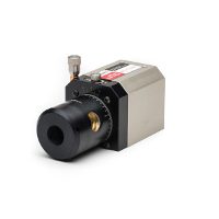
Laser alignment systems offer highly precise straightness and linear measurement for CNC equipment. These systems consist of a transmitter and receiver. The transmitter directs a laser beam across a shaft to the receiver, which sends data to a display or alignment software for data graphing and storage. The system replaces traditional references of piano wire and heavy steel straight edges to measure straightness to an accuracy of less than 0.001” over a longitudinal travel of 150 feet.
Aligning CNC Gantries
For large-format CNC gantries, geometric alignment is critical for meeting precision tolerances and minimizing maintenance expenses. Using a laser alignment system, you can verify rail straightness, squareness and parallelism of X, Y and Z axes as well as flatness. Below are best practices on how to conduct these measurements.
Rail Straightness:
This is the first performance check on a CNC gantry. With the receiver positioned at key checkpoints, rail straightness can be measured in horizontal and vertical directions. This is executed by using a 4-axis mount and tripod to position the laser so that the beam hits the receiver at both near and far references. The readings will show any misalignment to the reference line.
Squareness/Perpendicularity:
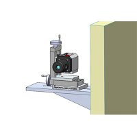
After verifying rail straightness, place the 90-Line Right Angle into the laser beam path to measure squareness among X, Y, and Z axes. The squareness of the Y axis (cross bridge) can be measured by positioning the receiver near one end and rotating the 90-Line nosepiece so the laser hits it. Zero the display, then move the receiver near the opposite end and rotate the nosepiece. The Vertical reading will indicate the distance that the Y axis is out of square.
Rail Parallelism:
CNC gantries with two longitudinal rails can be checked for parallelism using a 90-Line Right Angle. Horizontal and vertical readings will indicate the distance that a secondary rail is out of parallel. If the secondary rail is parallel to the first rail, readings should be equal along the length of the second rail..
Flatness:
Use the rotational mount to profile the flatness of tables and beds. Placing the laser transmitter onto the precision rotating base allows the laser to swing through a full circle and define a flat, precise plane of laser light. The plane of light is flat to within 0.001 inch over a 24-foot diameter area.

