Lathes, milling machines, jig borers, grinding machines, and other machine tools all have moving slides or tables that experience wear. Power failures, programming errors, and failing parts can result in machine tool failures and excessive damage to slides and ways when parts of the machine collide. Checking your machine tools for excessive wear and damage is easy and straightforward with a laser alignment system. These checks allow you to
- Assess the standard level of wear,
- Determine if damage has occurred to the machine,
- Provide information for repair, and
- Support ongoing preventative maintenance activities.
- Using a Laser Alignment System
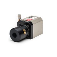
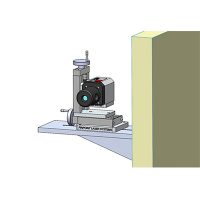
Setting up the laser alignment system on a machine tool is easy. In the following example we will show how a laser system is set-up and how measurements are taken on a milling machine X axis slide table. The laser transmitter is mounted on a tripod to the side of the machine tool and adjusted so that the laser reference beam passes over the top of the X axis slide being checked. A quick bucking in process helps align the laser so it is parallel with the travel of the table.
Next, a digital receiver is mounted on the table using a magnetic mount. This digital receiver is connected to a display unit that shows the position of the receiver left to right, as well as up and down. The display on the laser alignment system provides a precise readout accurate to 0.0001 inch (2.5 micron) in both of these directions.
As the slide table moves the receiver is able to continually check its position, relative to the laser reference beam. Any movements left and right or up and down are quickly seen and noted.
Quick alignment evaluations can be made by simply watching the laser alignment system display and slowly moving the table or slide along its travel and noting any variations in readings. The laser alignment system can also be attached to a computer for gathering and storing readings. The computer runs a simple software program known as Pinpoint Capture for the laser alignment system that records a number of readings per second as the slide table moves along. These readings can then be uploaded to popular spreadsheets or programs for further analysis.
Laser Alignment Systems In the Real World
In our example with the milling machine, the table has a 24-inch travel and we will set the computer to record 16 readings a second. We will adjust the speed of the slide table to travel at a rate of about 1 inch every 4 seconds. This will give us approximately 64 measurement readings per inch and a grand total of about 1,500 readings for the full travel of the slide table. This is a practical balance for the number of readings recorded and the level of detail needed for evaluating table alignment and runout using a laser alignment system. The Capture program is set to record readings into a designated text file and the recording started. The X axis slide is started as well and a full set of readings recorded. Our next blog entry will look at the recorded readings and analyze the performance of the slide table.
Contact our Pinpoint engineering team to discuss how Pinpoint Laser Systems can help you control precision and accuracy, as well as assess machine tool wear.

