When helicopters fly, it’s hard to miss the distinctive rotor blades on top. These blades form the main rotor system, creating the force needed to lift the helicopter into the air
At the tail end of the chopper, a smaller rotor, known as the tail rotor, prevents the helicopter from spinning while in flight. This tail rotor counteracts the torque created by the central rotor, generating thrust that pushes the helicopter in the opposite direction. By balancing the torque produced by the main rotor, the tail rotor ensures the helicopter maintains steering, a forward direction and remains stable when lifting off and landing.
Tail Shaft Alignment Ensures a Smooth Ride
The tail rotor is powered by a drive shaft or series of shafts that transmit power from the engine to the tail rotor gearbox. Proper alignment of these tail rotor shafts is crucial for smooth operation.
An improperly aligned or curved driveshaft can lead to vibrations and excessive wear on components on the shaft ends. As the helicopter’s tail boom flexes in flight, poorly aligned shafting can wear or develop reliability problems. Alignment should be a key consideration during helicopter assembly, maintenance and service of the drive shafts.
Challenges with Traditional Shaft Alignment
A wire or string method is popularly used to align the tail rotor shaft. However, it is time-consuming and imprecise. It typically requires the removal of the tail boom assembly and can take multiple workers up to a week to complete the alignment.
In addition, the wire method is tedious, involving a multi-step process that demands a high degree of skill to execute the complex shaft alignment procedure involving manual positioning of wire endpoints. The alignment involves a technician sighting a think wire passing through a small guide hold and results are subjective. A bent wire or one have imperfections can lead to inconsistent alignment results.
At best, the string method achieves an accuracy of 0.1” (2.5mm). If the wire becomes damaged or breaks, the entire alignment process must restart. Once shafts are installed, verifying the results is challenging.
Laser Alignment Improves Results
Laser alignment offers a more efficient, quantitative solution for tail rotor drive shaft alignment, providing more accurate and repeatable results. This method allows for measurements over long distances and delivers high-precision outcomes. It doesn’t require special skills to get consistently accurate results.
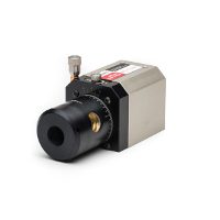
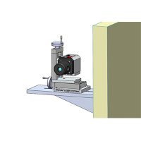
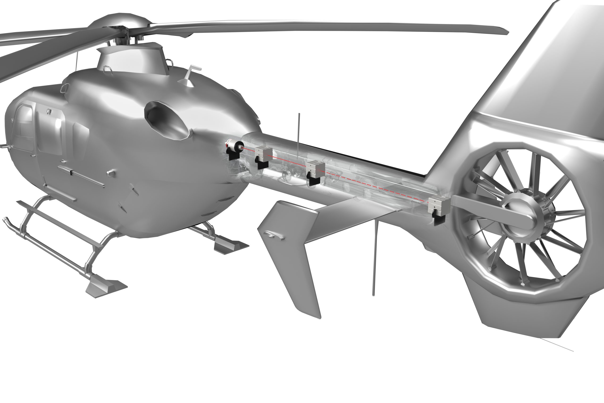
In this process, a laser reference beam replaces the wire. A transmitter, mounted on the forward end of the tail boom or the main gearbox drive flange, projects a laser beam that follows the same path of the wire with exceptional accuracy. Errors associated with sagging or swinging wire are eliminated.
A digital laser receiver takes multiple measurements, at each shaft bearing location, providing X and Y positions, as well as angular pitch and yaw measurements. A receiver can provide a measuring sensitivity of 0.0001 inch in X and Y and an accuracy of 18 arc-seconds for pitch and yaw.
Precision Output
Using a laser alignment system, shafts can be quickly measured and checked for misalignment. The digital precision of the laser system provides immediate feedback on how far and which way to move a shaft. Quantitative results can be downloaded into spreadsheets or software for calculating the required shims for support at different locations.
Laser alignment systems have been shown to save time by reducing manpower while offering real-time, precision feedback for tail rotor shaft alignment to ensure safe helicopter flight.


