About Helicopter Alignment
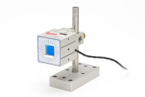
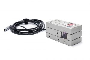
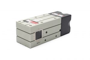
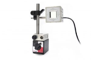
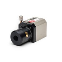
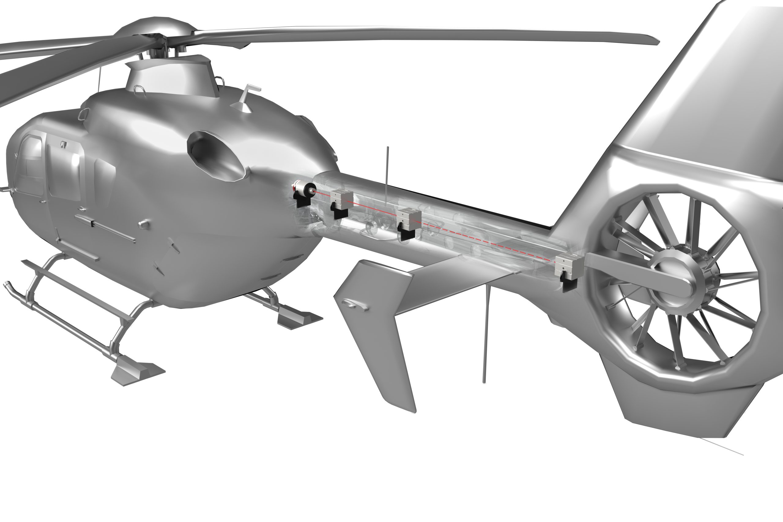
The Microgage laser alignment solution is used to replace the traditional wire with a laser beam and a digital laser receiver to preform tail rotor shaft alignment. To start, the laser would be mounted on the plate that is attached to the tail boom when it is removed from the helicopter. If the tail rotor driveshaft system were to be aligned with the tail boom in place, the laser could be attached to the drive phalange on the main gearbox.
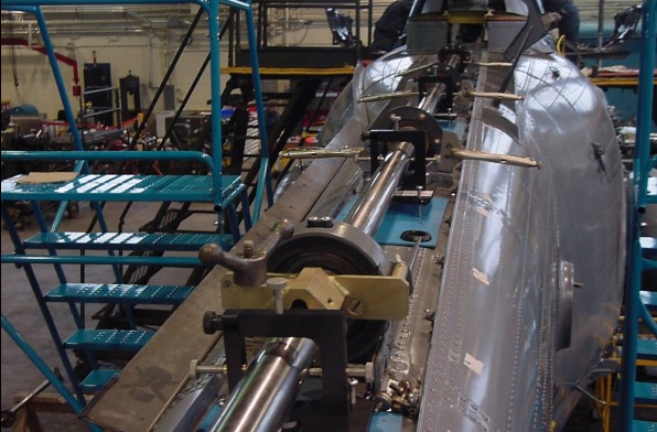
Helicopter Kit Details
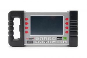
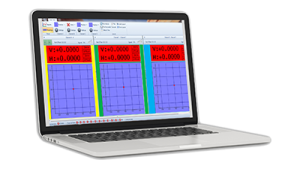
- PRO Smart display unit
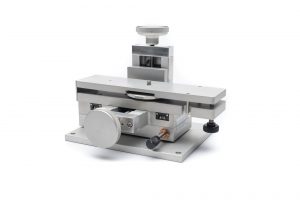
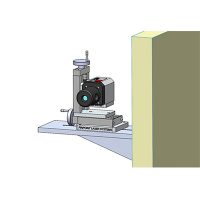
- 4-Axis Precision Mount
- Precision Tripod Mount
- Pinpoint CaptureTM software
- Wireless option for convenience
- Precise down to 0.0001 inch (depending on application)
- Quick return on investment
- Intuitive set up and use
- Improves efficiency and expands in-house capabilities
- Removes guesswork for alignment or measurement
- Minimizes machine downtime
- Supports preventative maintenance efforts
- Eliminates need for outside alignment contractors
- Reduces machinery installation costs
Measuring System
Specifications
Measurement resolution
0.0001″ (2.5 micron)
Measurement accuracy
± 0.0002″ or 1% of measurement (5 micron)
Operating distance
6” to 180”
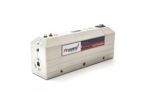
Laser Transmitter*
Specifications
Laser accuracy
≤ 2 arc-seconds
Laser level
10 arc-second, machinist grade
Laser source
laser diode, 636Nm, < 1mW
Laser repeatability
<1 arc-second
Laser dimensions
4.3” L x 2.6” D x 8.1”C
Laser housing
solid machined aluminum, hard anodized coating
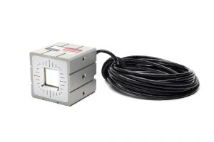
Receiver*
Specifications
Active detection area
(0.75″ x 0.75″ 19mm x 19mm)
Receiver housing
solid machined aluminum & hard anodized coating
Receiver dimensions
2.0” x 2.0” x. 20”, 2.0” x2.0” x 3.0” (wireless)
Smart Display
Specifications
Display configuration
hand-held, portable, self-contained
Resolution
0.0001″ (2.5 micron)
Units
inch, mm, mils, custom
Display
state-of-the-art, color, high-resolution, touchscreen
Controls
keypad, multifunction buttons, touchscreen
Storage
data readings & notes up to 10,000
Housing
solid machined aluminum, hard anodized coating

