Checking Roll Parallelism using the Microgage Laser
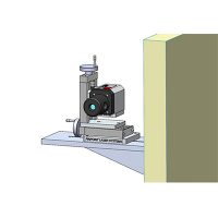
Measuring and aligning for parallelism has many practical applications across industry. The Microgage can establish parallel reference lines accurate to within 0.001 inch over considerable distances by simply moving the 90-Line to different positions along the laser path and using the receiver to make comparison measurements. For parallelism measurements, the 90-Line is moved sequentially along the laser path to create multiple reference lines, or planes, that are each square to the original laser reference line and parallel to each other.
Contact Pinpoint Laser Systems today! We have engineers standing by to answer any questions you may have (8AM – 5PM EST). 1-800-757-5383 (US) Call 1-978-532-8001
Video Tutorials
- 4-Axis Measuring & Alignment
- 4-Axis Mount
- Alignment Equipment Overview
- Bucking In & Measuring Straightness
- Capture Video Overview
- Disc Receiver Video
- 90 Line Accessory
- Buck-In Microgage Laser
- Scheduling an App Discussion
- Laser Microgage PRO
- Level with Pro-Line
- Leveler Rotational Mount
- Roll Leveling & Profiling
- Measuring Straightness
- Microgage 2D Overview
- Microgage 2D in Quality Digest
- Microgage 2D Kit
- Microgage 2D Roll Alignment
- Microgage 4D Receiver
- Microgage Adjustable Mount
- Microgage Cylindrical Laser
- Microgage Magnetic Mount
- Microgage PRO Overview
- Online Demonstrations
- Validation Procedure
- Performing Spindle Alignment
- Perpendicularity with Pro-Line
- Pro-Line Laser Kit Overview
- Receiver Bore Mount
- Roll Parallelism with Microgage
- Square & Parallel with Pro-Line
- Store Data on Microgage 2D
- Transfer Data from 2D
- Transparent Receiver
- Pinpoint Tripod
- Unboxing the Microgage 2D
- Unboxing the Microgage PRO
[/row]