Wear is a fact of life with moving machinery and as the precision slides, rails, guides, and bearings inside equipment become worn, the tight fit between moving parts is compromised and the accuracy and performance of the machine is degraded. This wear leads to runout and poorly made parts, machinery downtime, and lost profits. Keeping your machinery well aligned and running smoothly will improve your product quality, production efficiency, and boost your profits.
Runout describes the errors when a slide, moving table, or control mechanism is worn and will not run straight and true. Often on machine tools and production equipment a moving table will run straight for a portion of its travel and then shift or move off its correct linear path because the supporting bearings, slides, or ways underneath the table are worn causing misalignment. CNC machine tools that are constantly working on heavy parts, that are centered on the moving X-Y table, in the middle of the table’s range of travel will often experience heavy wear in this region. For this reason, the runout will likely be low at the far ends of the travel range, but in the middle of the travel range, excessive runout develops due to wear on the undercarriage, guide bearings, and ways. Similarly, when the ends of large parts are machined, the motion and wear is concentrated at the ends of the travel of the X-Y stage and this is where the runout occurs instead of in the middle region.
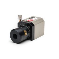
A laser alignment system can find and measure runout in machine travel to a precision of 0.0001 inch (0.003 mm) and can be configured to measure any axis of travel. Furthermore, connecting laser alignment equipment to a laptop or PC gives you an option for storing measurement points, analyzing your results, creating reports, and plotting runout where it exists in the travel of your moving slides and stages.
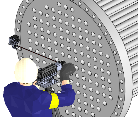
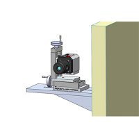
Here’s how it works: The laser is placed at the end of the moving slide, table, or axis that you want to check and the laser beam is adjusted until it runs parallel to the axis of travel as defined by two location points on your machine. The laser receiver is then attached to the moving table or slide and the display value is zeroed. The table or slide is then run through its full range of travel and the laser is adjusted until it reads zero at the far end of the slide travel. Now, moving the slide again, you can watch the value of the display for readings that vary from your zero setting. This technique is very quick and easy to use and provides precise measuring data about the runout and quality of your machine tool’s operation. Over time you can check your machine and then re-check it periodically to look for the rate of wear and develop an ongoing predictive maintenance schedule for that machine.