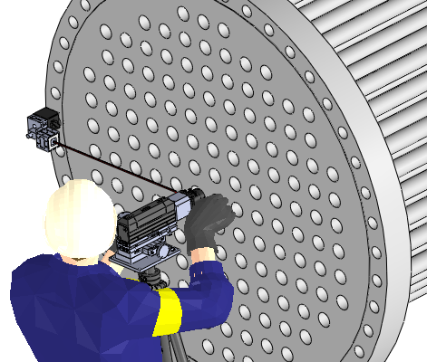
Recent MG-Pro wireless testing has yielded some information that may be useful to users.
Testing was initialized to determine the usable range for a wireless spindle alignment inquiry.
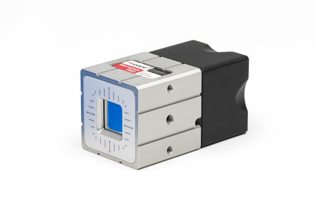
The PLS MG-Pro wireless receiver series is usable only with MG-Pro systems.
The Wireless function must be user-enabled for a MG-Pro Display to receive data from the receiver transceiver.
The MG Wireless laser receivers can operate on one of four frequency channels; ID_1, ID_2, ID_3, and ID_4. The MG-Pro display must be set for the same frequency channel.
This is set in the Home/Configure/Wireless screen of the display software.
Two channels cannot be utilized by one display, but rather different channels allow up to four displays to be used simultaneously in the same facility.
It is important that the AAA cell batteries in the wireless laser receiver are healthy and providing adequate current and minimum 2.7 VDC for the radios to operate.
As well, for best results the battery pack in the MG-Pro display should be charged to, or near to full capacity.
If either the display or the wireless laser receiver have low battery voltage levels the radio signals will either not pair up, drop the radio pairing and then start seeking another channel to pair with, or operate marginally providing an intermittent data stream potentially leading to unreliable readings.
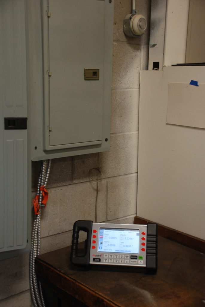
At present, the PLS MG-Pro wireless system has been tested to provide reliable measurements at distances of 25 meters (~82 feet) through moderate obstructions.
Moderate obstructions include: work benches, workers on duty, tools and fixtures, assorted shelving, electrical conduits and medium-weight machinery.
The wireless signal has difficulty passing through denser items such as filled file cabinet drawers, for instance. The laser receivers can transmit reasonably well from inside a closed metal desk drawer, but a file drawer filled with hundreds and hundreds of sheets of paper becomes too much of a signal choke and the pairing can sometimes be lost when passing behind such high density obstructions.
Some success transmitting readings from within 1.5m long section of steel pipe positions in some greatly obstructed confines and with the ends of the pipe blocked.
Further testing is now planned for longer pipe lengths and for a variety of materials.
The easiest way to determine if the radios are maintaining contact is to switch to the home screen on the display, and then switch back to the measure screen.
When the radios are operating properly, the measure screen will re-activate, the laser energy strength will rise to a ‘green’ percentage level, and the readings will actively fluctuate in the ten-thousandths column.
If the radio pairing is lost, the laser energy percentage level will remain red, the Vert. and Horz. readings not showing on the display screen. If this condition arises, the wireless system pairing must be redone.
If the readings remain on the display screen, but there is no fluctuation of the ten-thousandths column, the paring is likely lost and the display is simply showing the last reading it received.
This condition of no fluctuations of the ten-thousandths column, will also occur when the two AAA cell batteries in the laser receiver begin to run low on voltage. There can be enough energy in the two cells to pair up, but not enough current to transmit the collected data to the display.
To check wireless receiver module battery health, pair-up a receiver and then navigate to the Home/Configure/Wireless page of the display software.
There is a battery indicator shown in the center of the screen.
The battery indicator must show at least one bar green for the wireless system to operate and pair up. It is recommended that battery indicator is three to four bars green for taking readings reliability and for longer duration of measurements without interruption.
Note that with one bar green, the AAA cells are about 50% exhausted. These will still operate flashlights, and wall clocks, etc. But don’t be fooled; wireless transmission requires more energy than those other devices do.
To initiate the system switch on the MG-Pro display and verify the wireless function is enabled.
Next, switch on the wireless module of the laser receiver. The LED indicator will blink green once indicating ID_1 channel, for four or five times and then switch to red.
At this time the MG-Pro display will request a receiver number be assigned to the receiver. Select 5, 6, 7, or 8 and Apply. When pairing is successful the display will report that the wireless receiver is on-line.
To re-initiate the system after pairing is dropped switch off the laser receiver wireless module and switch it back on.
The best practice is to ‘power down’ the receiver from the wireless display screen in the display software because in this way the software immediately knows the wireless is nullified and makes the same receiver channel available for re-use.
If the receiver is switched off from the momentary switch on the receiver itself, the software has to assess there is a problem, and then it may take longer for the processor to report the wireless is off-line.
After switching back on by the momentary switch, the display will ask for a receiver assignment number once again and re-connect.
Sometimes the display is not satisfied that receiver 5 will not be re-energized (ie: after changing of batteries, etc.), so the software withholds the same receiver number and then offers the others 6, 7, and 8 as options.
To avoid all the built-in logic, power down the receiver module from the software.
Once the system has been paired a few times and users become familiarized with the steps it will become very easy to use.After some practice, the wireless system will provide greater usefulness to the user because of the greater lengths at which readings can be taken.