About Bore Alignment
Product # – PR-B091
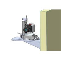
The Pinpoint Microgage System is an ideal solution to solve any bore alignment issues. It works by placing a laser transmitter is outside the bore and a laser aimed so that the beam passes through the center of two datum areas along the bore path. The laser beam is then adjusted so that the beam passes through the center of each bore datum. Once this is established, you can check the position of multiple bore surfaces to the centerline of the laser beam.
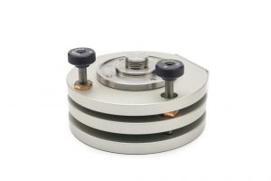
We also offer a number of different size cylindrical laser transmitters and receiver mounts that can be inserted right into bore tubes if needed.

Bore Alignment Details
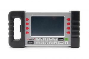
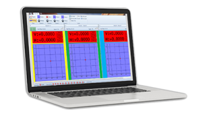
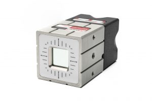
- PRO Smart display unit
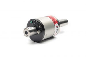
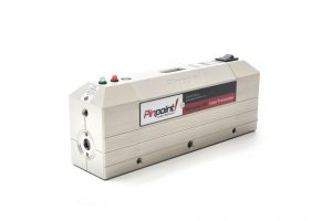
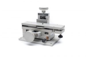
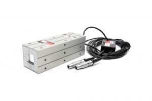
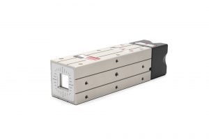
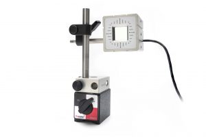
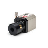
- Laser Transmitter
- Pinpoint Capture™ software
- Wireless option for convenience
- Precise down to 0.0001 inch (depending on application
- Quick return on investment
- Intuitive set up and use
- Improves efficiency and expands in-house capabilities
- Removes guesswork for alignment or measurement
- Minimizes machine downtime
- Supports preventative maintenance efforts
- Eliminates need for outside alignment contractors
- Reduces machinery installation costs
- Adjusting bar feeders and spindle alignment
- Aligning propeller shafts
- Positioning rudder posts
- Aligning pistons in pump assemblies
- Adjusting extrusion press rams in their boxes
- Aligning screw drives in plastic and slurry extrusion mills
- Periscope and precision antenna alignment
- Other alignment applications
Measuring System
Specifications
Measurement resolution
0.0001″ (2.5 micron
Measurement accuracy
± 0.0002″ or 1% of measurement (5 micron)
Operating distance
6” to 180”
Laser Transmitter*
Specifications
Laser accuracy
≤ 2 arc-seconds
Laser level
10 arc-second, machinist grade
Laser source
laser diode, 636Nm, < 1mW
Laser repeatability
<1 arc-second
Laser dimensions
4.3” L x 2.6” D x 8.1”C
Laser housing
solid machined aluminum, hard anodized coating
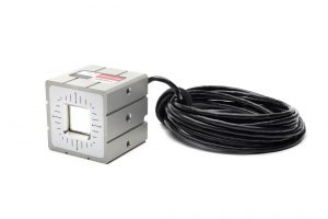
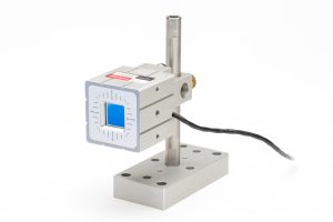
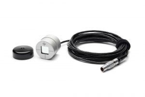
Receiver*
Specifications
Active detection area
(0.75″ x 0.75″ 19mm x 19mm)
Receiver housing
solid machined aluminum & hard anodized coating
Receiver dimensions
2.0” x 2.0” x. 20”, 2.0” x2.0” x 3.0” (wireless)
Smart Display
Specifications
Display configuration
hand-held, portable, self-contained
Resolution
0.0001″ (2.5 micron)
Units
inch, mm, mils, custom
Display
state-of-the-art, color, high-resolution, touchscreen
Controls
keypad, multifunction buttons, touchscreen
Storage
data readings & notes up to 10,000
Housing
solid machined aluminum, hard anodized coating