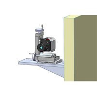
Laser Microgage alignment application for aligning 11 bore tubes in a pitched, radial orientation for blast furnace operations.
A customer approached Pinpoint’s engineering team with an application to align 11 bore tube gas furnace jet nozzles in a radial formation with a 15 degree pitch angle. This assembly delivers ultra-high heating capability to a continuous process production line. Each nozzle tube is 7 inches in diameter and approximately 4 feet on length. The alignment challenge is to position the end of the tube in the correct radial X/Y location and also to provide a pitch angle of 15° and a horizontal yaw angle that is parallel to a common center point in the middle of the furnace area.
The illustration on the right is a top view showing 11 bore tube assemblies, each pointing inward to the center of the furnace area. In addition to their radial position, a pitch orientation needed to be set as well. The work environment was at room temperature but the various surfaces were scaled and covered with carbon and debris. In addition to the alignment work, the customer also needed to provide documentation on the final position and alignment of each tube assembly.

Pinpoint Solution:
Several customer conference calls were held to understand the critical alignment and measurement needs, then to recommend a measuring system, followed by documentation software, and finally to develop a working alignment procedure. Pinpoint’s Laser Microgage system was selected for this application in the following items were added to make the measurement;
- Laser Microgage 2D system with the 4 Axis Microgage 4D Receiver upgrade
- Leveler Rotational Mount
- Pinpoint Precision Tripod
- DCU Computer Interface
- Pinpoint Capture software
- Large Diameter Bore Mount
- 15 Degree Wedge angle for laser transmitter
- Microgage 4D Receiver Bore Mount
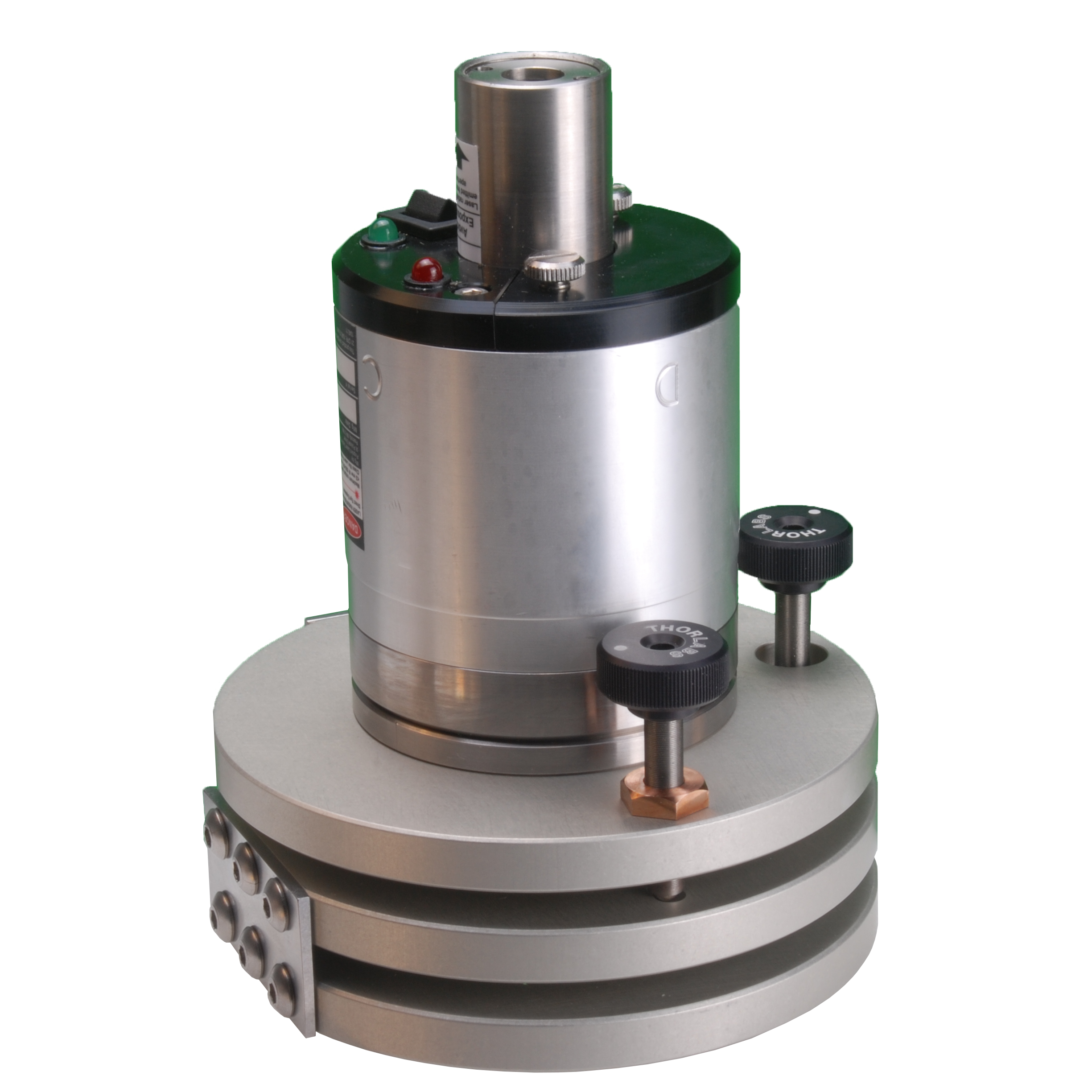
For the alignment, the Microgage laser transmitter is placed onto the precision Leveler Rotational Mount, which is securely mounted on a tripod in the exact center of the furnace area. By adjusting the three precision leveling screws, the Leveler mount is aligned into a level, flat plane. If the laser was placed on the mount at this time, the laser beam would trace a flat plane that is level to gravity. Next, the 15° wedge mount is placed onto the Leveler and the laser transmitter is secured on top of this wedge mount. Now, the laser transmitter, on top of the Leveler Rotational Mount, can be turned through a full circle and the laser reference beam points upward at a precise 15° angle. The photograph, above, shows the laser transmitter secured to the 15° mounting wedge and secured on top of the Leveler Rotational Mount.


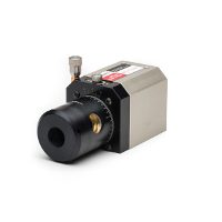
This alignment application requires lateral measurements, and alignment, in the horizontal and vertical directions (X/Y) and also their angular components; pitch and yaw. The Microgage 4D Receiver is an optimal choice for this measurement because it provides XY readings as well as the two angular components for pitch and yaw.
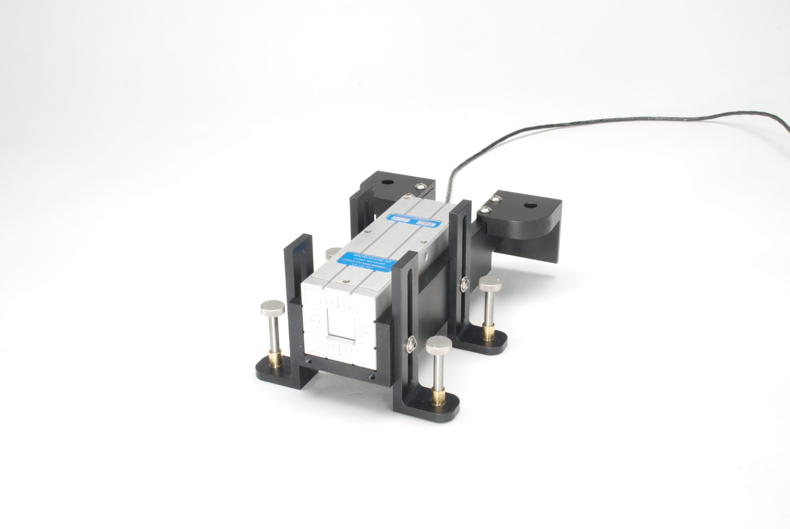
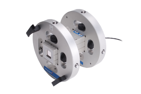
The Microgage 4D Receiver is mounted into a bore mount consisting of two circular plates that locate to the forward and back ends of the Microgage 4D Receiver housing. On the edge of each circular plate there are two precision tooling balls, at a right angle to each other, and on the opposite side of the plate are two spring-loaded ball plungers. This design allows the fixture to be pressed into the bore tube so that it will register on the interior wall and be held in place by the opposing spring-loaded ball plungers. The fixture is designed to hold the Microgage 4D receiver in the exact center of the bore tube.
For aligning each bore, the Microgage laser transmitter is rotated 60° and positioned for each bore tube alignment. Next, the bore tube is adjusted up and down, as well as left and right until the X/Y lateral reading on the Microgage Display reads a 0.000 position for both readings. This ensures that the end of the tube is in the correct position relative to the center of the furnace. The final step is pivoting the bore tube in the vertical pitch axis and in the yaw axis until these angular readings equal zero degrees on the Microgage display. This process is repeated moving around the interior of the furnace area until all of the bore tubes are aligned correctly in their radial positions and with the appropriate angular orientation.


During the alignment process, readings were shown on the Microgage display for real time adjustments and also recorded. At the conclusion of the alignment process, the Microgage readings for X, Y, Pitch and Yaw were uploaded using Pinpoint Capture and imported into an Excel spreadsheet showing the existing orientation and the final as built welded position for each bore tube assembly.
This alignment system has been used many times for both new installations and also for repair and service work. Modifications can be easily made to adapt to different furnace configurations and user applications.
Technical Specifications
- Fabricated From Machined And Hard Anodized Aluminum
- Configurable For Multiple Bore Sizes
- 8 Hardened Tooling Balls To Index Tube Wall
- Spring Ball Plungers To Provide Grip
- Aluminum Hand Grips for Handling
- Easy To Use And Durable Design

More Custom Samples
Looking for Something Custom? We’ve Got You Covered.
Contact us at (800) 757-5383 or fill out the form to get started with a custom solution for your business!
[formidable id=56]